1. Setting Welding Schedules
77
ML-2050A/2051A/2150A
Chapter 2 Various Settings
Introduction Part
Installation and
Preparation Part
Operating Part Maintenance Part Appendixes
<Note>
When the pulse width setting range is switched, the set values of SCHEDULE are
initialized. To prevent misoperation, the setting cannot be changed unless No.8
of SW1 is set to ON. When the setting of No.7 of SW1 is changed and the ENTER
key is pressed, the setting of No.8 of SW1 is returned to OFF. It takes about 15
seconds until initialization is completed. The POWER lamp blinks during that time.
Turn o the power supply after blinking stops.
3
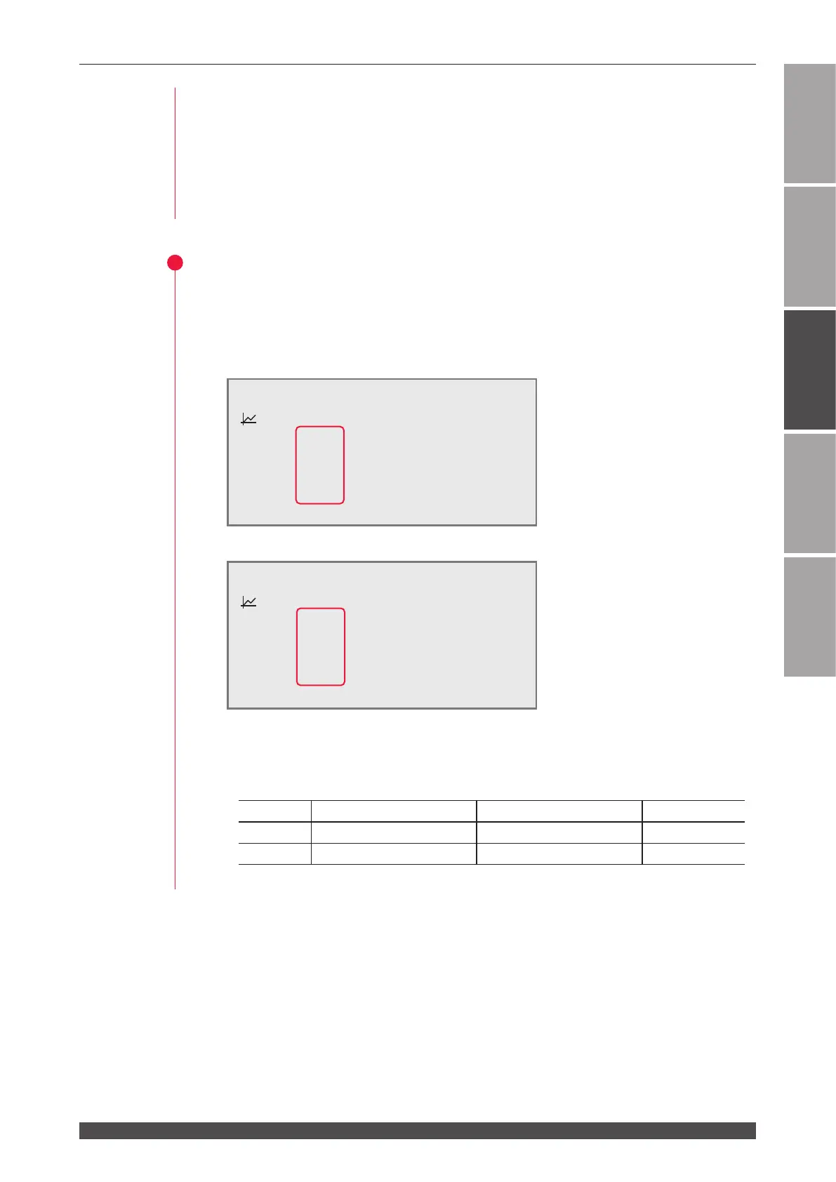
Setting the Setting Denitively
(1) Press the ENTER key to denitively perform the setting.
The pulse width setting range on the SCHEDULE screen is switched.
Setting example before switching (SW1-7 OFF)
Setting example after switching (SW1-7 ON)
⇒
On the FLEX screen, the setting range is switched and displayed in the same way.
<Notes>
- The value of "FLASH1" + "FLASH2" + "FLASH3" of the SW1-7 setting is as follows.
Setting Maximum value (ms) Minimum value (ms) Step (ms)
ON 5.00 0.20 0.02
OFF 10.0 00.2 00.1
- Set the values of output time in 0.02 ms step after the SW1-7 setting.
-SCH.#00 [FORM:FIX ]
≃
11.4J WATER
28˚C
:OFF PEAK=02.00kW REPEAT= 00pps
k
SLOPE 00.5ms
SHOT =0000
FLASH1 01.6ms 040.0%
FLASH2 02.2ms 100.0%
FLASH3 01.2ms 020.0%
m
SLOPE 00.7ms
HV:OFF POSI.BLINK:OFF POSITION:OFF
-SCH.#00 [FORM:FIX ]
≃
11.4J WATER
28˚C
:OFF PEAK=02.00kW REPEAT= 00pps
k
SLOPE 0.00ms
SHOT =0000
FLASH1 0.00ms 000.0%
FLASH2 0.00ms 000.0%
FLASH3 0.00ms 000.0%
m
SLOPE 0.00ms
HV:OFF POSI.BLINK:OFF POSITION:OFF