86
ML-2050A/2051A/2150A
4. Setting the Function of the Output Unit with Fiber Sensor (Option)
Operating Procedure
(1) Set the ber breakage detecting function.
Remove the side cover of the main unit and set No.3 of SW1 to ON.
The fiber breakage detecting function is set. When optical fiber breakage or
end face damage is detected during laser light output, Error No.38 to 40 FIBER
SENSOR 1 to 3 TROUBLE is displayed.
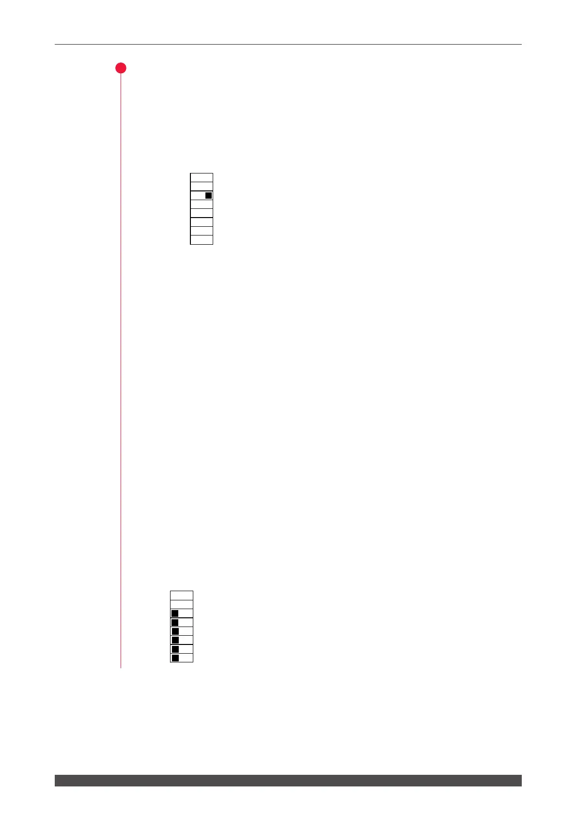
SW1
Set No.3 to ON.
⇒
Do not touch switches No.1 and No.2.
(2) Set the ber mount checking function.
Out of No.3 to No.5 of SW2, set all of the output unit numbers to be used to OFF
and set the others to ON.
The fiber mount checking function is set. When the optical fiber or trouble
detecting cable is not connected, Error No.32 FIBER SWITCH TROUBLE is
displayed.
⇒
Set the ber mount checking function after setting No.3 of SW1 to ON to set the
ber breakage detecting function.
(3) Set the LED ON checking function.
Out of No.6 to No.8 of SW2, set all of the output unit numbers to be used to OFF
and set the others to ON.
The LED ON checking function is set. When the LED (HV-ON lamp) ON status
of the specied output unit is not checked, Error No.33 E.INDICATOR TROUBLE
(OUTPUT UNIT) is displayed.
⇒
Set the LED ON checking function after setting No.3 of SW1 to ON to set the
ber breakage detecting function.
As an example of (2) and (3) settings, set No.3 to No.8 of SW2 to OFF to use output
units No.1 to No.3.
SW2
3: Checking that ber 1 is mounted.
4: Checking that ber 2 is mounted.
5: Checking that ber 3 is mounted.
6: Checking that the ber 1 HV-ON LED is ON.
7: Checking that the ber 2 HV-ON LED is ON.
8: Checking that the ber 3 HV-ON LED is ON.
1
2
3
4
5
6
7
8
O
F
F
1
2
3
4
5
6
7
8
O
F
F