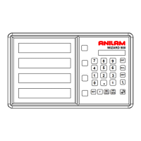
137
Output Connections (With I/O Option Only)
Output connections are located on the back of the DRO. When DRO functions are
activated, the DRO generates signals through these connections to operate external
devices.
Each output can sink 500 mA of current when active. The output load of Relay 1 and
Relay 2 should be a maximum of 10 VA (maximum 20 Volts, 0.75 A).
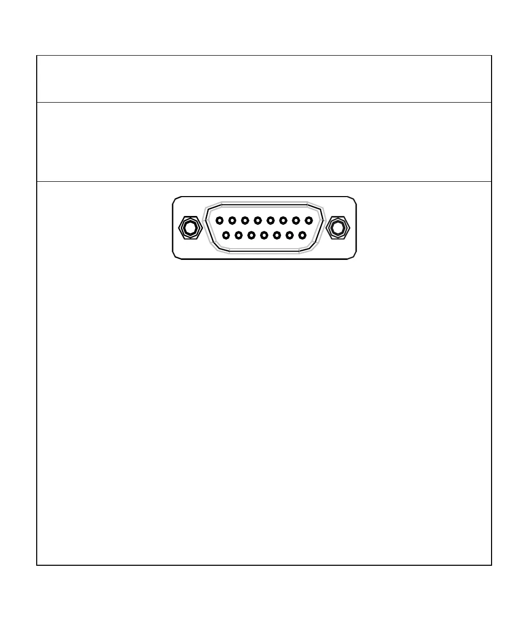
1 2 3 4 5 6 7 8
9 10 11 12 13 14 15
DA 15 Connector (Male)
Pin 1 Relay 1 Output Pin 9 Relay 2 Output
Pin 2 Relay 1 Output Pin 10 Approaching Zero
Pin 3 X-Axis Zero Pin 11 Y-Axis Zero
Pin 4 Z-Axis Zero Pin 12 Relay 2 Output
Pin 5 W-Axis Zero Pin 13 Ground
Pin 6 Ground Pin 14 +24 Volts
Pin 7 +24 Volts Pin 15 DAC Output for CSS
Pin 8 Analog Ground for DAC Output (0-10 Volt/10mA, 12 Bit, galv.
isolated)
The output connections, X-axis zero, Y-axis zero, Z-axis zero, W-axis zero, and
approaching zero are enabled by applying a constant +24 VDC, 50 mA source to pin 7
and pin 14 and a ground to any of two ground pins.
When outputs are enabled, pin 3, pin 4, pin 5, and pin 11 generate a 24-V common
signal as the corresponding axis value is zero. Pin 10 generates a 24-V common signal
within a set range of an axis zero. The 24-V common output is generally used to
complete a relay control circuit.