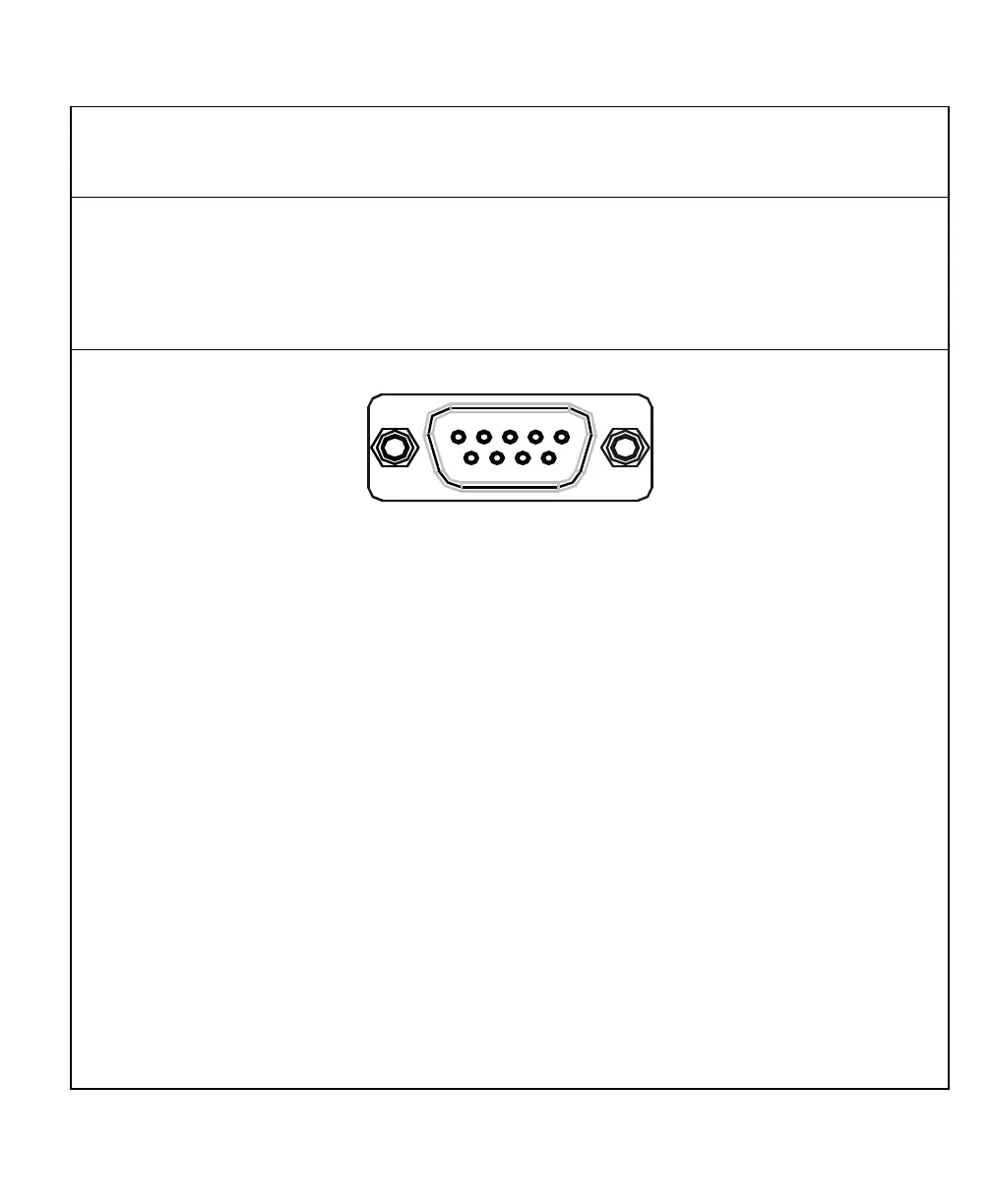
138
Input Connections (With I/O Option Only)
Input connections are located on the back of the DRO. These connections allow signals
from external devices to activate specific DRO functions.
DRO functions are activated by applying a +24 VDC, 10 mA signal for a minimum of
100 ms. Inputs to the DRO are optically coupled for protection. The Ground pin is the
reference ground for the inputs and should always be used.
32 41 5
6 7 8 9
DE 9 Connector (Male)
Pin 1 X-Axis Zero
Pin 2 Z-Axis Zero
Pin 3 Recall (RCL Key for remote operations)
Pin 4 First-Spark Detection (900E Only)
Pin 5 Ground
Pin 6 Y-Axis Zero
Pin 7 Store (ENT Key for remote operations)
Pin 8 Print
Pin 9 W-Axis Zero