6-26 Replacing Fan Assembly – ND70948 Assembly Removal and Replacement, MS202xC
6-60 PN: 10580-00307 Rev. D MS20xxC MM
6. The VNA PCB Assembly is connected to the Mother Board and the SPA PCB with several cables. Some of
the cables are shown in Figure 6-24 on page 6-63. None of these cables are disconnected during Fan
Assembly replacement. Observe all cables as the VNA PCB Assembly is moved and then replaced. Take
care not to stress any of these cables.
7. Lift the top edge of the VNA Assembly (with the attached top connector panel) and carefully move the
VNA Assembly up and in the direction of the top of the case in order to expose the cable connection for
the Fan Assembly, connector J1002 on the Mother Board. Note that the VNA PCB Assembly and the
SPA PCB Assembly cables are not shown in Figure 6-23.
8. Gently pry the fan cable from Mother Board connector J1002. Refer to item 2 in Figure 6-23.
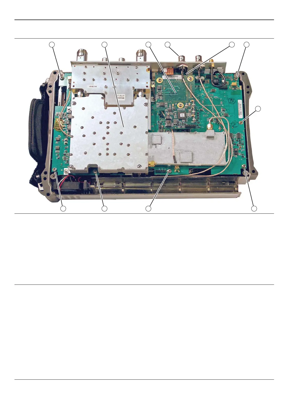
1. VNA PCB Assembly and related RF Shields with eight (8) total mounting screws
2. Location of Power Monitor Assembly PCB Option 5 with three (3) Phillips-head mounting screws
3. Remove the castellated nut and loosen the Ext Trig Input BNC Connector before removing Power Monitor PCB
4. The first VNA PCB Assembly Phillips-head mounting screw under Power Monitor PCB
5. Screws 5, 6, 7, 8, 9, 10, and 11. Additional Phillips-head mounting screws (7 total) holding VNA PCB Assembly
in place
Note that cables in this figure may not match newer VNA Master MS202xC instruments. Refer to Figure 6-15
on page 6-33.
Figure 6-22. VNA PCB Assembly Screw Locations

 Loading...


