Chapter 4 INTERFACE SETTINGS
175
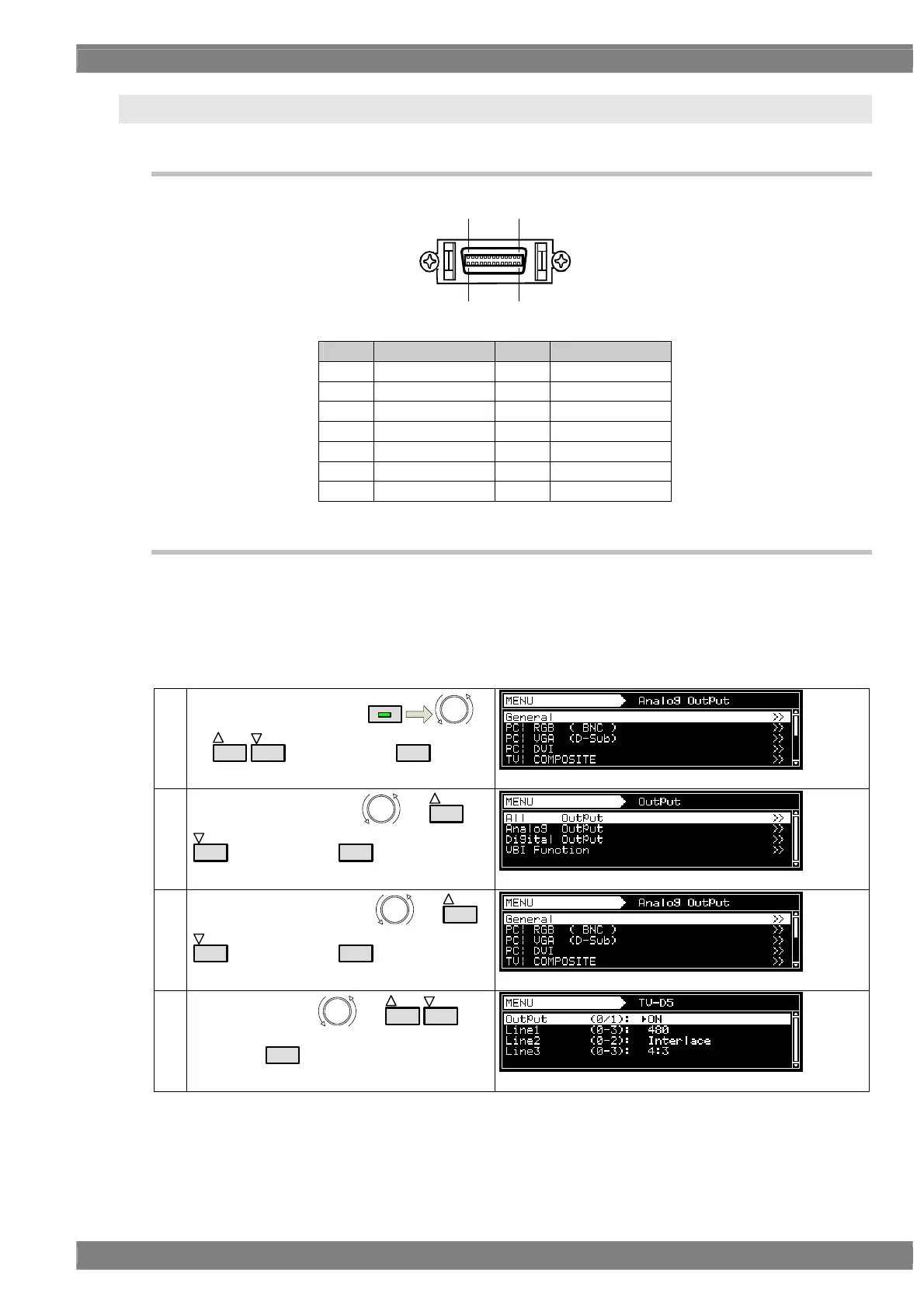
4.9 D5 (D connector)
4.9.1 Connectors and pin assignments
Pin no. Signal Pin no. Signal
1 Y 8 Line 1
2 GND (Y) 9 Line 2
3 Pb 10 NC
4 GND (Pb) 11 Line 3
5 Pr 12 NC
6 GND (Pr) 13 NC
7 NC 14 NC
4.9.2 ID signals
ID signals indicating the resolution, scanning system and aspect ratio can be output from the D
connector. The ID signals are DC signals, and they identify the formats using three lines. These lines
are referred to as line 1, line 2 and line 3.
Setting procedure
(1)
Select Program Edit using
MENU
or
INC
DEC
, and then press
SET
.
(2)
Select Output (TIM) using
or
INC
DEC
, and then press
SET
.
(3)
Select Analog Output using
or
INC
DEC
, and then press
SET
.
(4)
Select TV|D5 using
or
INC
DEC
, and
then press
SET
.
71
14 8