Chapter 4 INTERFACE SETTINGS
43
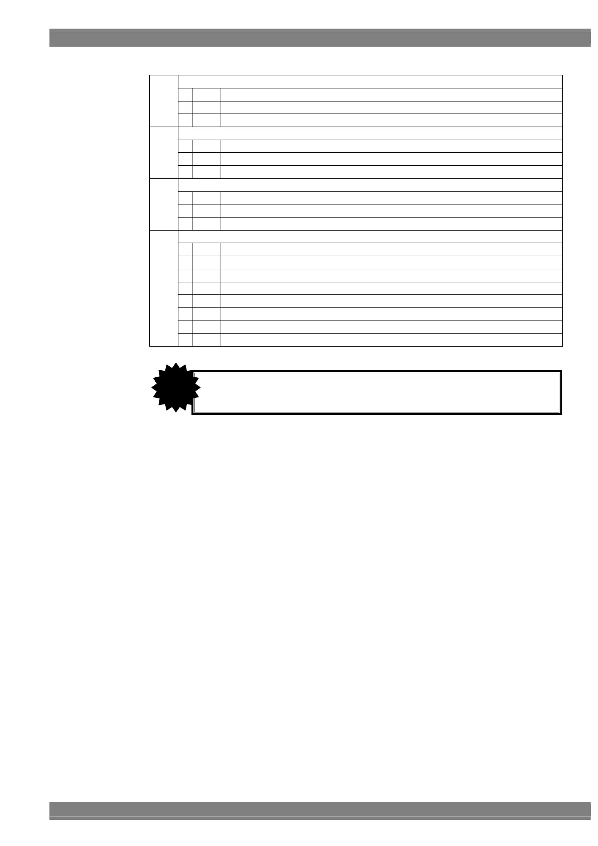
<Sync setting parameters>
Used to set the HS connector output.
0
Off
No output
1
Nega
The signal is output with a negative polarity.
HS
2
Posi
The signal is output with a positive polarity.
Used to set the VS connector output.
0
Off
No output
1
Nega
The signal is output with a negative polarity.
VS
2
Posi
The signal is output with a positive polarity.
Used to set the CS connector output.
0
Off
No output
1
Nega
The signal is output with a negative polarity.
CS
2
Posi
The signal is output with a positive polarity.
Used to set whether to superimpose Video-on-Sync onto the analog component signals.
0
Off
Video-on-Sync is not superimposed.
1
R
Video-on-Sync is superimposed onto the R analog component signal.
2
G
Video-on-Sync is superimposed onto the G analog component signal.
3
RG
Video-on-Sync is superimposed onto the RG analog component signal.
4
B
Video-on-Sync is superimposed onto the B analog component signal.
5
RB
Video-on-Sync is superimposed onto the RB analog component signal.
6
GB
Video-on-Sync is superimposed onto the GB analog component signal.
CV
7
RGB
Video-on-Sync is superimposed onto the RGB analog component signal.
• If the CS signal is a tri-level sync (HDTV timing) signals, its polarity cannot be
changed.
CAUTION