Tightening
328 9836 3521 01
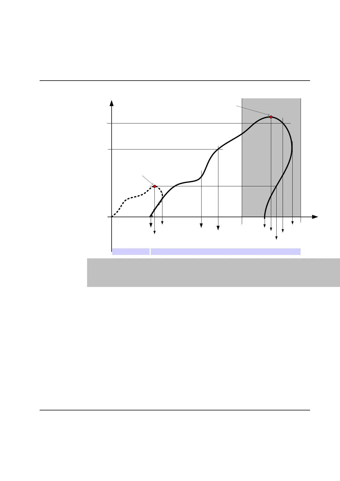
Diagram:
Torque
TStart Torque Start A_Tstart Start cond. - Angle at Tstart F Stop cond. - Final angle
TStop Torque Stop AS1 Start cond. - Angle at step start SO Stop cond. - Shut-off angle
AL Angle Low AS2 Start cond. - Angle at prev. shut off P Stop cond. - Peak angle
AH Angle High AS3 Start cond. - Peak angle prev. SOP Stop cond. - Shut-off angle prev.
A_Snug Start cond. - Snug point A_Tstop Stop cond. - Angle at Tstop
Angle
Previous step
AS1
AS2
AS3
TStart
A_Tstart
Shut-off point
F
SO
P
SOP
TStop
A_Tstop
AL
AH
Step xStep x-1
Shut-off point
A_Snug
Result var.: A (step angle)
Alarms: Step angle high (AH) and Step angle low (AL).
Trace: AH and AL are shown in trace as horizontal lines from check start to stop, which vary
according to selected start and stop conditions. The lines are only shown when Angle vs.
Time is selected and Check limits are enabled in the trace form (see View of trace curves).
 Loading...