Peripheral Devices
600 9836 3521 01
8.15.2 Interface definition output
Two output maps are defined in the PowerMACS, one for systems with up to five (5) spindles and one for
systems with up to sixteen (16) spindles. Only one of the maps can be enabled at a given time. The maps
are enabled/disabled manually by changing the PLC bytes Out parameter. All outputs are stable for at
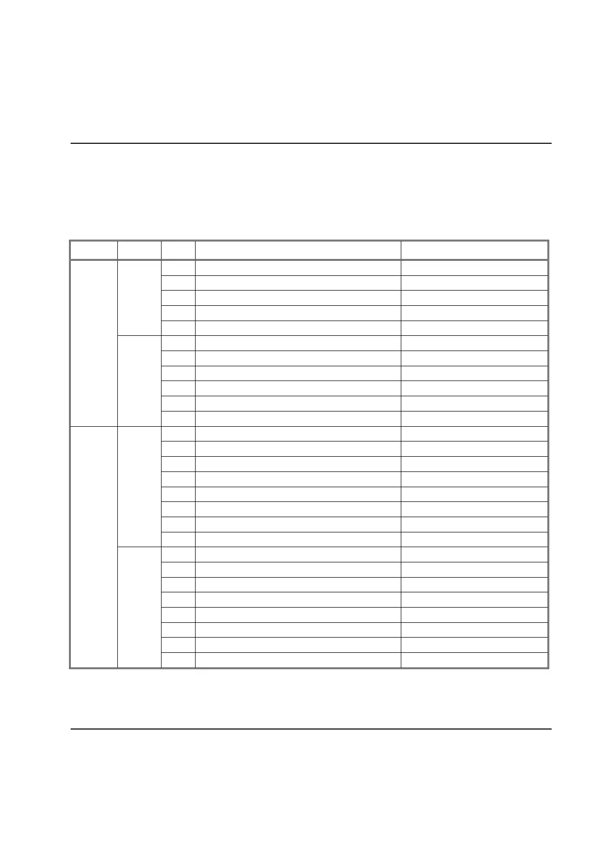
least 500 ms. The output map definition for signals from PowerMACS is according to the following table:
Spindle – Mode Set Code (0-7)
Spindle – Error Proofing Ready (EPR)
Spindle – 1 Good Rundown (Green Light)
Spindle – 1 Remove (Red Light)
Spindle – 1 Low Torque (Yellow Light)
Spindle – 2 Good Rundown (Green Light)
Spindle – 2 Remove (Red Light)
Spindle – 2 Low Torque (Yellow Light)
Spindle – 3 Good Rundown (Green Light)
Spindle – 3 Remove (Red Light)
Spindle – 3 Low Torque (Yellow Light)
Spindle – 4 Good Rundown (Green Light)
Spindle – 4 Remove (Red Light)
Spindle – 4 Low Torque (Yellow Light)
Spindle – 5 Good Rundown (Green Light)
Spindle – 5 Remove (Red Light)
Spindle – 5 Low Torque (Yellow Light)
Note! The above shows the output for a system with up to 5 spindles. For a system with up to 16
spindles just continue the table with spindle 6, and so on.
 Loading...