Tightening
9836 3521 01 365
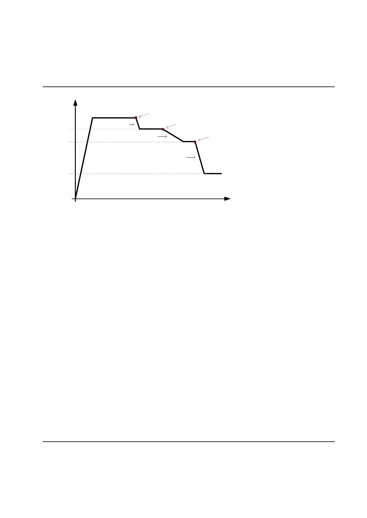
Time
Speed
Speed 1
Down ramp 1
Down ramp start point 1
Speed 2
Speed 3
Down ramp 2
Down ramp 3
Down ramp start point 2
Down ramp start point 3
6.5.6.2 Ramps & Other – Other
The Other group holds parameters that do not belong to the earlier parts.
Specify in Start delay for step if you want a delay first in the step, before the main function starts.
If the checkbox Wait for PLC at step end is checked for at least bolt in the cycle the station will stop and
wait for the signal INTERMEDSTART from the PLC to continue running the cycle. This works like an
implicit synchronization point. Even if the step is lacking the synchronization point it will still report to the
station and wait for all other spindles.
In Torque Spike Elimination specify the angle for which all torque readings should be disregarded for
control.
Note! The torque restriction (see chapter: Fail Safe Torque) is active also during the Torque Spike
Elimination phase.
Use the Customer step name combo to select the customer error code series that shall be used in this
step. See Set Customer step names and Set Customer error codes for more information about this
function.
By checking Hold position when stopped the bolt will be held in the position it has when zero speed is
detected. This option cannot be used together with the Hold torque stop condition.
Using the Stop method property you can set up how you want to stop the spindle when the target for the
step has been reached:
Inertia brake. Choose this alternative if you want to stop as quickly as possible. This is the
recommended stop alternative for fastening.
Ramp down the current. First lower the current to X % of the current value at target (Initial
value), and after that ramp down the current with the Slope [A/s]. Use this alternative to relax any
torsion built up in a controlled manner.

 Loading...