Peripheral Devices
484 9836 3521 01
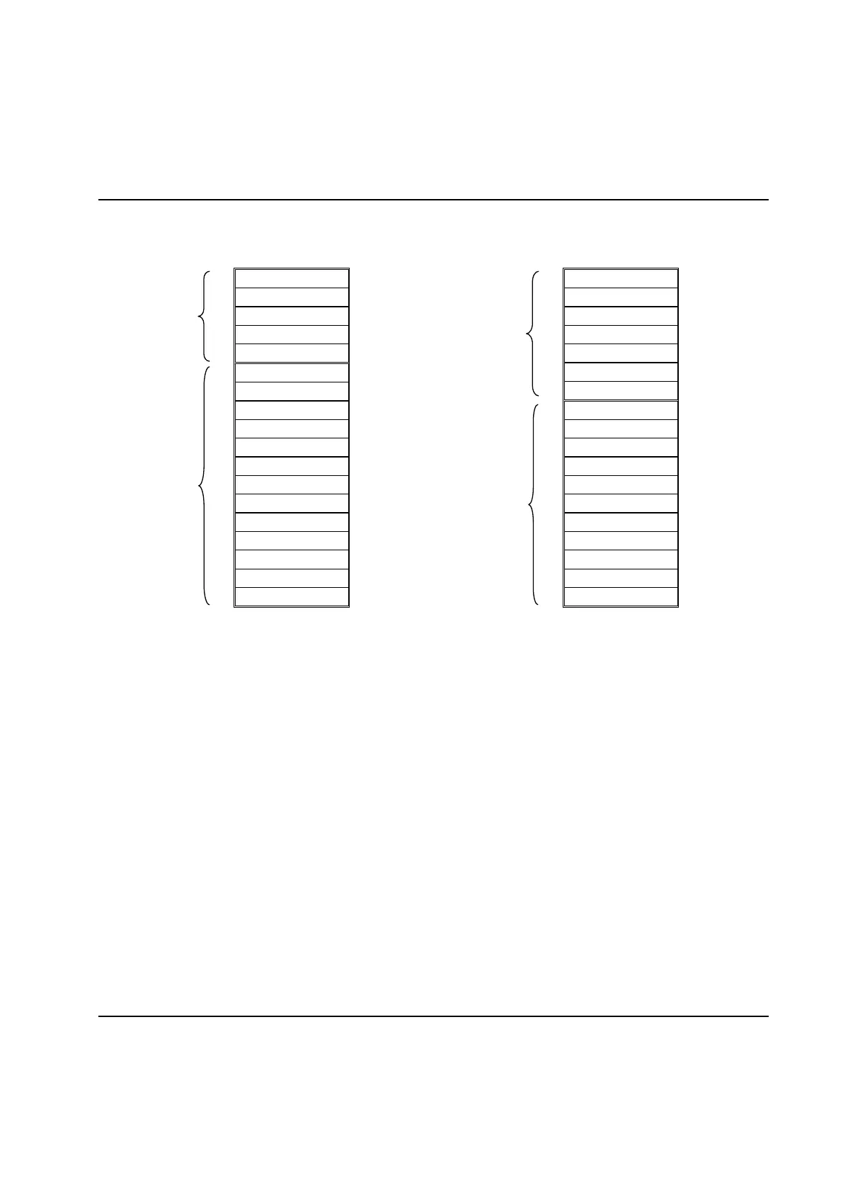
The below picture shows how the input and output areas are divided using the parameters:
Inputs to the
PowerMACS PLC
Size =
Fast bytes In
Used as Process
Data input, e.g.
to request next
cycle data.
Size =
Data bytes In
Outputs from the
PowerMACS PLC
Size =
Fast bytes Out
Used as Process
Data output, e.g.
the requested
cycle data.
Size =
Data bytes Out
Note! You should not configure the respective input and output areas bigger then what really needed. The
reason for this is that all bytes you set up here will be transferred over the fieldbus, regardless if
they are used by the application or not.
If you want to transfer Process data over the fieldbus then you must create a Fieldbus-Reporter. How to
do this, and connect it to your fieldbus device, is described in the New reporter chapter. How to make the
Reporter format the result as you wish is described in chapter: Edit reporter.
Indication of the fieldbus status
When connected to a target system you can study the current status of the module using the
 Loading...