Peripheral Devices
496 9836 3521 01
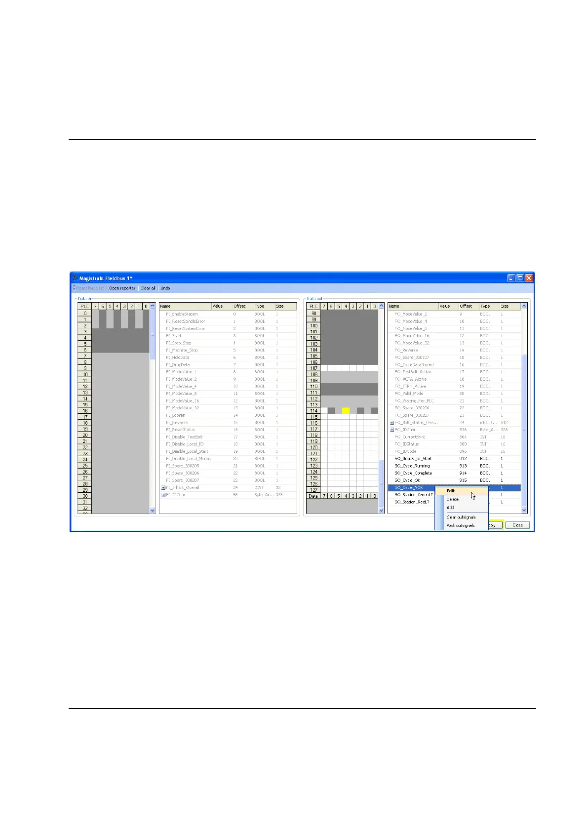
The form shows a listview and a memory grid each for data in and data out. The form represent the
signals in the Fieldbus_Variables group in the PLC.
When clicking on a cell in the grid, the mapped signal is highlighted in the listview and the whole signal is
highlighted in the grid. When clicking on a signal in the listview, the signal is highlighted in the grid.
Mapping of PLC signals can only be done when not connected to a TC. Monitoring and forcing of PLC
signals can only be done when connected.
Data bytes can not be set up in this form. A link to the reporter form is available on the command bar. Only
monitoring is available for the data bytes.
Mapping of signals
When not connected to a TC, PLC signals is added either by dragging them from the dynamic tool, which
will have one list of the available insignals and one list of the available outsignals, or by right-clicking one
of the listviews.
By right-clicking a signal in any of the lists, the user can choose to edit the offset, delete signal, clear all
signals in that list, or add new signals. The alternative Pack signals in the context menu will fill holes in the
map by moving all signals towards offset 0. Signals can also be dragged and dropped if the user wants to
change the order of the signals.
The "data" part of the grids will show nothing during the mapping phase.
 Loading...