Peripheral Devices
9836 3521 01 533
Likewise a variable declared at the logical address 2500 is mapped to address 0 of the output area of the
device. For best performance you should not define bigger areas than necessary.
When the variables are declared you are free to refer them from any POU (Program Organisation Unit)
you have, or will, declare in the project.
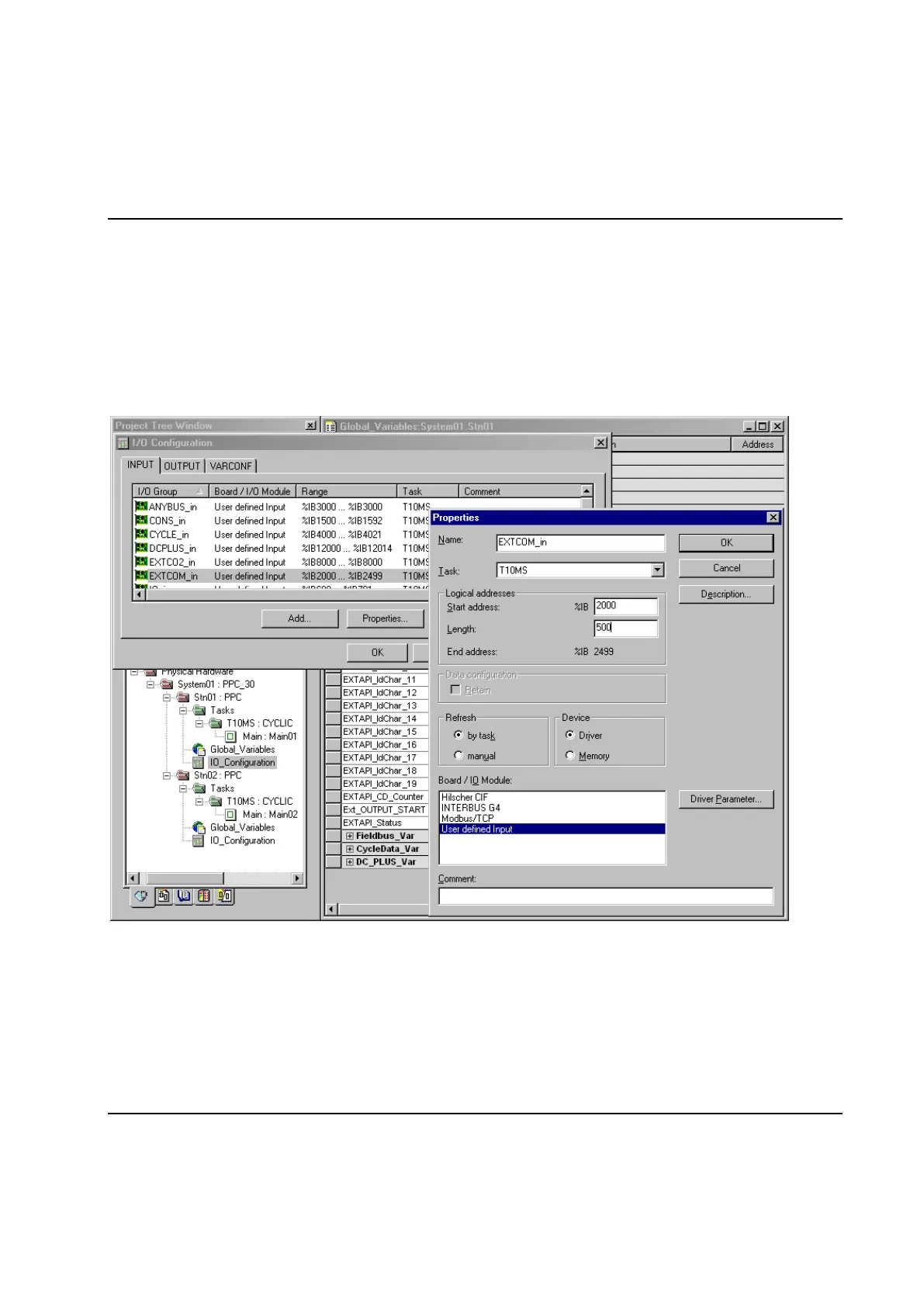
After mapping the input and outputs variables the next step is to configure the EXTCOM and/or EXTCO2
driver(s) to copy the input and output data from the external communication device to the PLC and vice
versa. This is done using the I/O Configuration dialogue which is invoked by double-clicking on the icon for
IO_Configuration worksheet of station to which the device is connected.
In the I/O Configuration dialogue first select the INPUT tab, mark the I/O Group EXTCOM_in or
EXTCO2_in and press the Properties button.
Change the value of Logical addresses – Length so that it corresponds to your needs. See How to map
input and outputs below for a description of the possible choices.
Then configure the copying of output data by selecting the EXTCOM_out or EXTCO2_out I/O Group on
the OUTPUT tab of the I/O Configuration dialogue and pressing the Properties button.
 Loading...