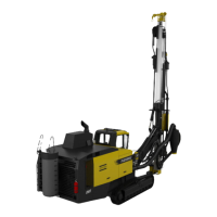
SmartROC D65 Tier 4 Final 2 General
19
Points to be observed when welding
n Grind off rust and paint from the area that is to be welded and carefully prepare the
joint.
n Weld in a dry area.
n Connect the welding ground cable to a clean surface as close as possible to the weld-
ing area. Avoid welding close to bearings and bushes. If these cannot be removed,
connect ground cables on both sides of the weld.
n Alterations and reinforcements must not be made without previous consultation with
Atlas Copco.
n DO NOT weld the hydraulic oil tank, valve block, compressed air tank, pressure lines
or the engine exhaust cleaning unit (CEM).
n See separate instructions for diesel engines for work on the exhaust cleaners soot
sensors.
n Welding on the exhaust cleaning unit frame and bracket is prohibited.
n Always keep a fire extinguisher for oil fires near at hand during all types of welding,
cutting and grinding. Screen off the work area from flammable materials.
n Always protect hoses, cables and electric components.
n Grind off spatter after welding. If possible, also grind the surface of the weld smooth
and treat it with anti-corrosion paint.
Electrode recommendations
Use only intact and clean electrodes that have been stored in a dry place. The generally
recommended type of electrode is ESAB OK 48.00, ESAB OK 48.30 or the equivalent in
accordance with the standard below:
ISO: 2560 E51 5B 120 20 H
SS: 14 3211 H10
DIN 1913: E51 55 B10
AWS: A/SFA 5.1 E 7018
Table3: Electrode recommendations
The use of MIG welding equipment is perfectly acceptable. The generally recommended
type of electrode is ESAB-OK Autrod 12.51 or the equivalent in accordance with the stand-
ard below:
SS: 14 3403 3423
DIN 8559: SG 2
AWS: A/SFA 5.18: ER 70 S-6
Table4: MIG electrodes
If in any doubt, contact Atlas Copco for advice.
2.1.11 Welding CAN BUS
Preparations before welding
Disconnect the supply voltage to all modules, both + and -, as follows:
n Cable KC50A is removed from the right-hand rear pillar outside the cabin.
n Cable KC50B is removed from the right-hand rear pillar outside the cabin.

 Loading...