SmartROC D65 Tier 4 Final 14 Options
203
Pin Function
5 GND
Table25: Pin configuration
14.2.4 Resolver module
Checking resolver inputs X6 - X9
Pin configuration:
Pin Function
1 Ref +
2 Ref -
3 Sine signal
4 Sine GND
5 Cosine signal
6 Cosine GND
Table26: Pin configuration
1.
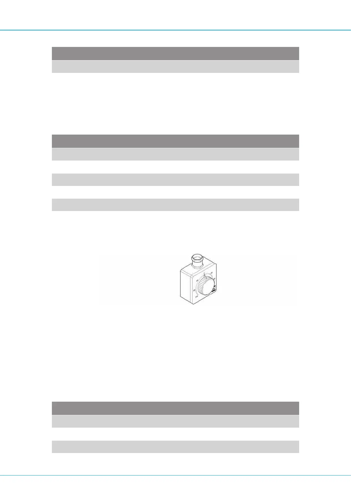
Connect the resolver tester to the relevant cable. Turn the test sensor slowly and
check that the angle shown on the sensor menu changes.
Resolver tester
If the angle changes, the sensor on the boom is faulty.
If the angle does NOT change, the cable on the boom must be checked.
2.
Connect the test sensor and test cable directly to the resolver module input. Turn the
test sensor slowly and check that the angle on the sensor menu changes.
If the angle changes, the cable on the boom is faulty.
If the angle does NOT change, the resolver module is faulty.
Checking the encoder input (Pulse sensor input) X10
Pin Function
1 +15V
2 +15V
3 Signal A
4 GND

 Loading...