SmartROC D65 Tier 4 Final 14 Options
204
Pin Function
5 Signal B
6 GND
Table27: Pin configuration
1.
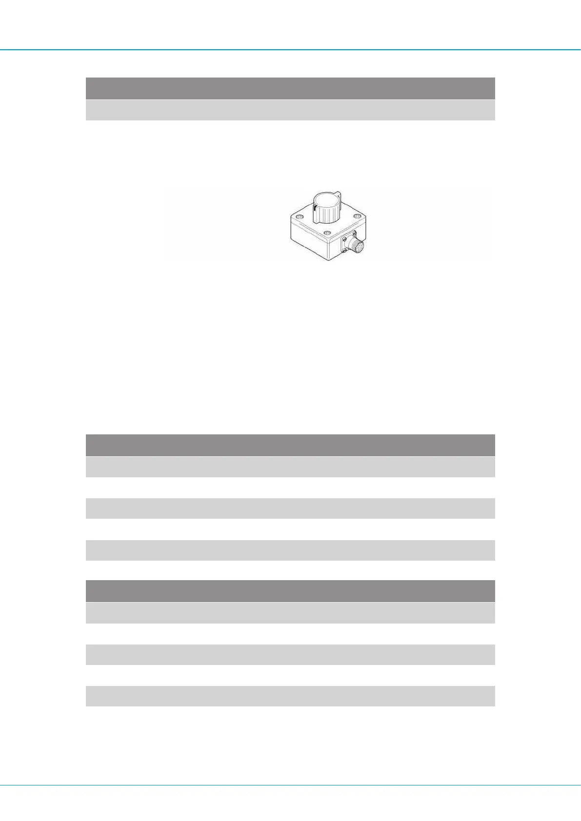
Connect the encoder tester to the end of the relevant cable. Turn the test sensor
slowly and check that the length measurement shown on the sensor menu changes.
Encoder tester
If it changes, the sensor on the boom is faulty.
If it does NOT change, the cable on the boom must be checked.
2.
Connect the test sensor with test cable directly to the resolver module input. Turn the
test sensor slowly and check that the length measurement shown on the sensor menu
changes.
If the measured value changes, the cable on the boom is faulty.
If the measured value does NOT change, the resolver module is faulty.
Checking analogue input channels X11 and X12
Pin Function
1 GND
2 + 4.5V power supply out
3 Signal in
4 (Not used)
5 (Not used)
Table28: Pin configuration for input channel X11
Pin Function
1 GND
2 + 15V power supply out
3 Signal in
4 (Not used)
5 (Not used)
Table29: Pin configuration for input channel X12
1.
Connect the resolver module connector X11 or X12 to test box connector (B).

 Loading...