SmartROC D65 Tier 4 Final 14 Options
202
Pin Function
1
2 out +B
3 out -B
4 out +A
5 Out -A
Table24: Pin configuration
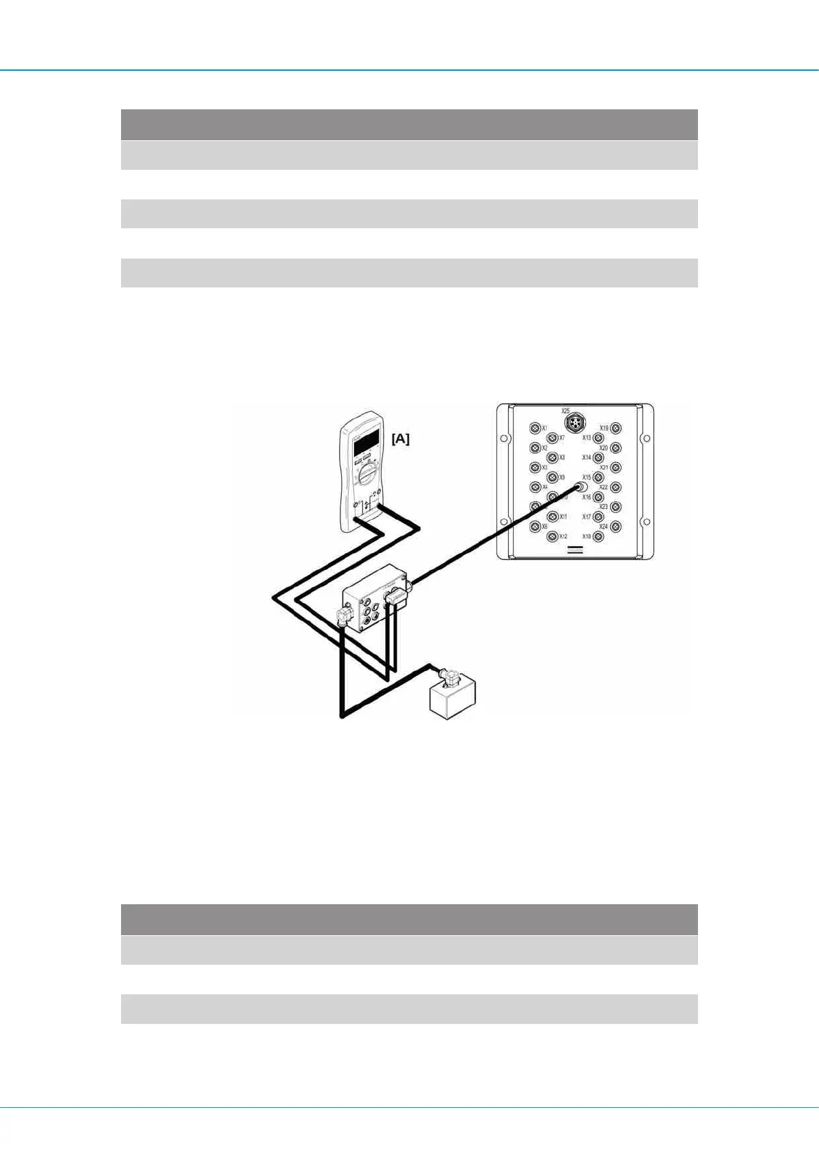
Measuring current
1.
Connect the 5-position connector on the I/O tester between the output of interest on
the I/O module and the valve as illustrated.
Connecting the I/O tester
2.
Connect the multimeter in series with the +A or +B output that is of interest.
3.
Actuate the function and check that the current corresponds with the actuated value
on the display.
Encoder inputs (pulse sensor) X12, X18
Each encoder connector has two signals, A and B.
Pin Function
1 +24V DC
2 B
3 GND
4 A

 Loading...