DL205 User Manual, 4th Edition, Rev. D
4-53
Chapter 4: System Design and Configuration
1
2
3
4
5
6
7
8
9
10
11
12
13
14
A
B
C
D
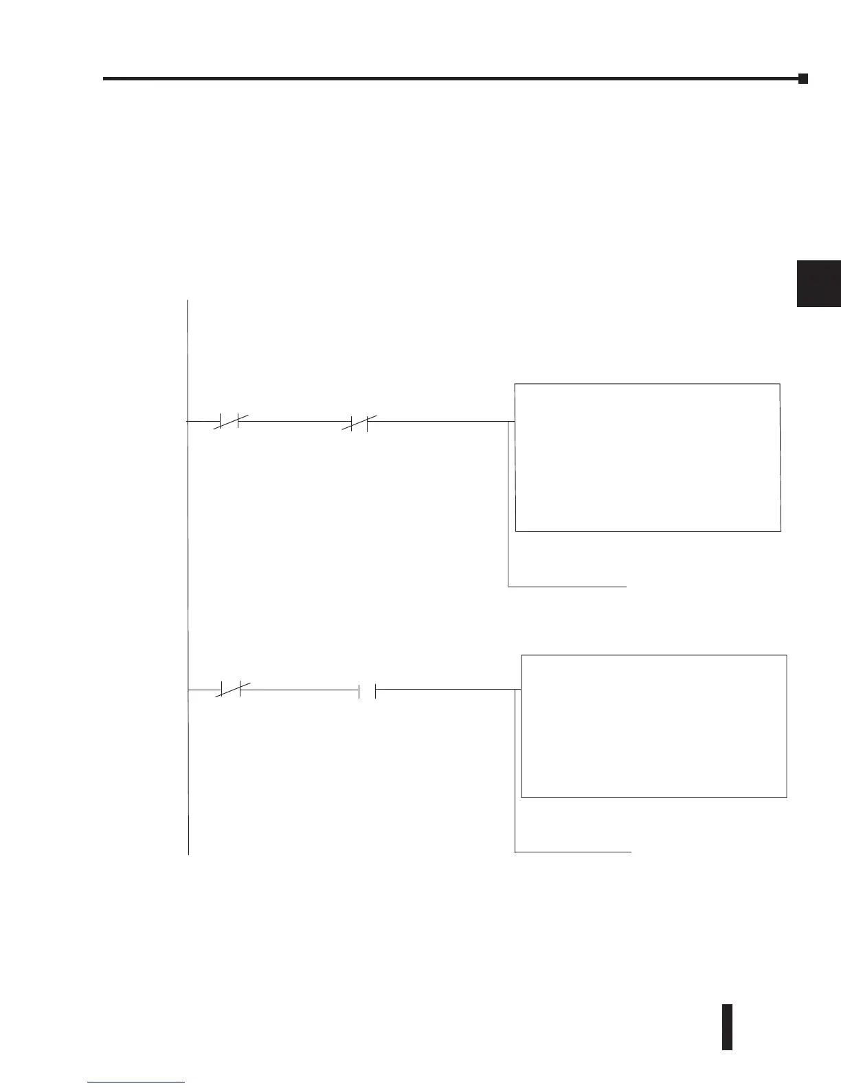
If you are using multiple reads and writes in the RLL program, you need to interlock the
routines to make sure all the routines are executed. If you don’t use the interlocks, then
the CPU will only execute the first routine. This is because each port can only handle one
transaction at a time. In the example, rungs 3 and 4 show that C100 will get set after the RX
instruction has been executed. When the port has finished the communication task, the second
routine is executed and C100 is reset. If you’re using RLL
PLUS
Stage Programming, you can
put each routine in a separate program stage to ensure proper execution and switch from stage
to stage allowing only one of them to be active at a time.
SP116 C100
SP116
C100
MWX
Port Number: K2
Slave Address: K1
Function Code: 06 - Preset Single Register
Start Slave Memory Address: 40001
Start Master Memory Address: V2000
Number of Elements: n/a
Modbus Data Type: 584/984 Mode
Exception Response Buffer: V400
Instruction interlock bit
C100
( SET )
( RST )
C100
Instruction interlock bit
MRX
Port Number: K2
Slave Address: K1
Function Code: 01 - Read Coil Status
Start Slave Memory Address: 1
Start Master Memory Address:
This rung does a Modbus write to the first holding register 40001 of slave address number one.
It writes the values over that reside in V2000. This particular function code only writes to one
register. Use function code 16 to write to multiple registers. Only one Network Instruction
(WX, RX, MWX, MRX) can be enabled in one scan. That is the reason for the interlock bits. For using
many network instructions on the same port, use the Shift Register instruction.
This rung does a Modbus read from the first 32 coils of slave address number one.
It will place the values into 32 bits of the master starting at C0.
3
4
Port 2 Busy bit Instruction Interlock bit
Port 2 Busy bit Instruction Interlock bit