DL205 User Manual, 4th Edition, Rev. D
1-11
Chapter 1: Getting Started
1
2
3
4
5
6
7
8
9
10
11
12
13
14
A
B
C
D
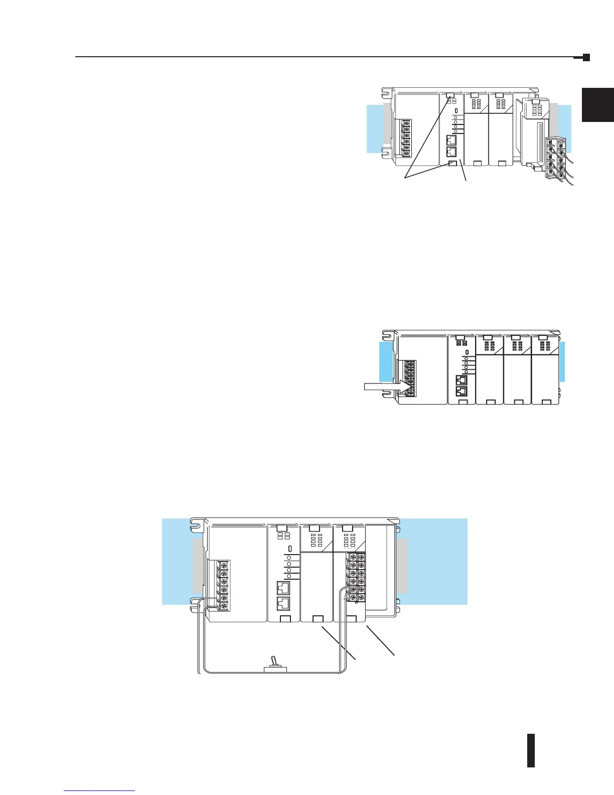
Step 2: Install the CPU and I/O Modules
Insert the CPU and I/O into the base. The CPU must be inserted into the first slot of the
base (next to the power supply).
• Each unit has a plastic retaining clip at the top and
bottom. Slide the retainer clips to the out position
before installing the module.
• With the unit square to the base, slide it in using
the upper and lower guides.
• Gently push the unit back until it is firmly seated in
the backplane.
• Secure the unit to the base by pushing in the retainer clips.
Placement of discrete, analog and relay modules is not critical and may go in any slot in any
base; however, for this example, install the output module in the slot next to the CPU and the
input module in the next slot. Limiting factors for other types of modules are discussed in
Chapter 4, System Design and Configuration. You must also make sure you do not exceed the
power budget for each base in your system configuration. Power budgeting is also discussed
in Chapter 4.
Step 3: Remove Terminal Strip Access
Cover
Remove the terminal strip cover. It is a small
strip of clear plastic that is located on the base
power supply.
Step 4: Add I/O Simulation
To finish this quick start exercise or study other examples in this manual, you will need to
install an input simulator module (or wire an input switch as shown below), and add an output
module. Using an input simulator is the quickest way to get physical inputs for checking out
the system or a new program. To monitor output status, any discrete output module will work.
Wire the switches or other field devices prior to applying power to the system to ensure a
point is not accidentally turned on during the wiring operation. This example uses DC input
and output modules. Wire the input module, X0, to the toggle switch and 24VDC auxiliary
power supply on the CPU terminal strip as shown. Chapter 2, Installation, Wiring, and
Specifications, provides a list of I/O wiring guidelines.
Toggle switch
Input
Module
Output
Module
CPU must reside in first slot!
Lift off
Retaining Clips