PAGE 77
Windows PC Software
– Call Number (level triggered):
Same function as above, however, except that here the level is analyzed
and not the edge.
– Disconnect: By enabling this function a connection on the indicated
line (1 or 2) can be disconnected.
– Load Preset: Via this function you can load a Preset which you must
indicate under Preset.
– Backup Alarm Signal: With this function it is possible to feed in an ex-
ternal TTL alarm signal whereby an ISDN backup (see
CHAPTER4.7.2.1.4, Page 55) is established.
– Backup Disable: Via this external control signal you can avoid that an
ISDN backup is established although the Backup Alarm Signal is ac-
tive (see CHAPTER4.7.2.1.4, Page 55).
– Set Information Base Entry: Spezial function for projects.
– String Command: Spezial function for projects.
Example:
With TTL1 a call is to be accepted on line 1. The system is to be confi-
gured automatically to the MPEG 1B Mode. After the conversation is
over, the connection is to be dropped also with TTL1.
Programming:
Positive egde:
Funktion Code: Call Number
Line: 1
Transmission Mode: MPEG 1B
Phone Number: -
Negative egde:
Function Code: Disconnect
Line: 1
FIG. 49 FUNCTION SEQUENCE OF THE EXAMPLE
TIP
With this function, you can configure an automatic redialling to ensure that
the partner is automatically re-dialled if there is an unexpected disconnec-
tion. Please configure this function under Positive edge. Since the TTL Pin
has a 5V level by default, a connection to the given number is established im-
mediately.
Attention: This function can only be ended by setting the Pin to the 0V level
or switching off this function via the configuration.
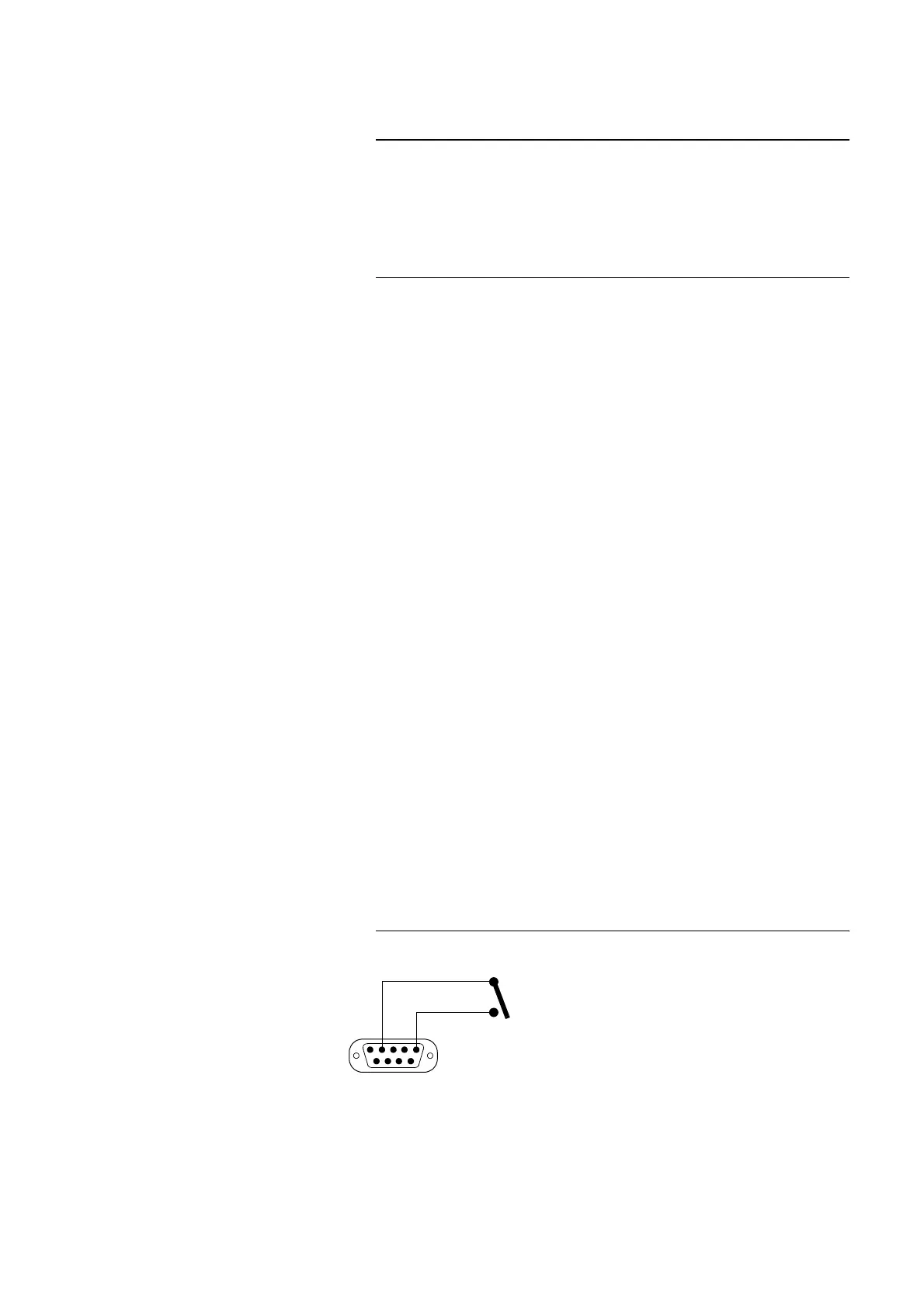
1
5
6
9
9-pol. SUB-D male
to MAGIC DC7/AC1
(TTL/RELAY)
Switch is open:
Pin 2 = TTL 1 lies at +5 V (via internal 10 KOhm series resistor)
Switch is closed:
Pin 2 =TTL 1 is set to 0V (Pin 5):
existing connection is dropped
Switch is opened:
Pin 2 =TTL 1 is set to+5V:
Incoming call is accepted and connection is established
Switch