134
STATUSAERIAL
33. STATUS 550 DIGITAL
ANTENNA SYSTEM
FrequencyRange: UHF470–860MHz
FM88–108MHz
DAB175–230MHz
Antennaforwardgain 7db
Ampliergain 16db
Gainadjustment 15db
Noisegure 2.8db
Outputimpedance 75ohms
Output 95dbuv
Powersupply 12–24vDC
Powerconsumption 55ma
Signaloutputs 2TV1Radio
Travelling
!
Donottravel:
•Withtheantennaraised.
•Withtheantennasetforverticalsignals.
•Whentravellingadjusttheantennasothatit
pointstotherearofthevehicletoreduce
thepossibilityofdamagewhentravelling.
Operating
•Firstlydeterminetheapproximatelocation
of the nearest transmitter and whether
the signals are horizontally or vertically
polarised. For assistance ask your site
operator or check other antennas in the
vicinity.
1. Loosen the mast locking collar and raise
theantenna.Rotatethemasttodirectthe
antennatowardstheTVtransmitter.
2.TheH/Vindicatoronthebottomofthemast
indicatesthebackoftheantenna.
3.Should you need to receive vertically
polarised signals rotate the winder anti-
clockwisetotilttheantennathrough90º.
4.DONOTuseundueforceonthewinder.
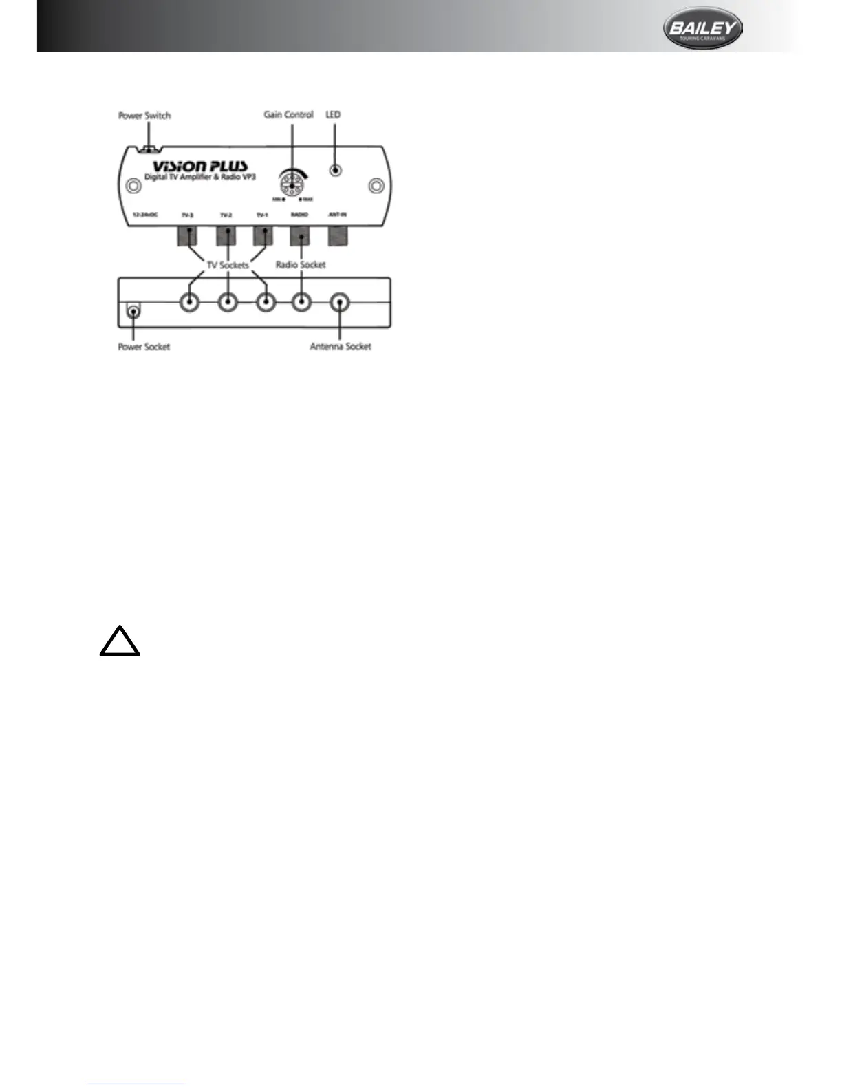
5.Switch ON the amplier and the LED will
illuminate.
6.Check thegaincontrolis settomaximum.
Formaximumrotateclockwise.
7. Tune your television into the strongest
signal.Youmayneedtoadjustthedirection
of the mast to achieve the best picture
quality.
8.Securebytighteningthemastlockingcollar.
DAB and FM Radio Operation
Status is designed to receive DAB and FM
when connected to a radio with DAB/FM
facility.
Dependent on location, DAB and FM reception
may be improved by setting the antenna to
vertical.
Fault Finding
The following are some of the key areas we
suggestyoucheck which generallysolvethe
mostcommonproblemsencounteredwiththe
operationoftheStatusantenna.
Coaxialconnections
Itiscriticalthatallconnectionsinthesystem
arettedcorrectly.
Gain Control
In normal use the button should be rotated
clockwiseformaximum.Instrongsignalareas
theamplicationmayneedtobereduced.To
reduce amplication rotate the button anti-
clockwiseuntilpicturequalityimproves.The
buttonrotatesthrough270°fromMAXtoMIN.
LED Light
Should the LED on the amplier not light,
rstly check there is power to the unit.
Secondly check the polarity is correct.
Otherwise contact Grade UK Ltd for further
assistance.
Short Hook Up–Test 1
Thistestisolatesthewiringfromtheamplier
throughtoyourTV/radiopoints.
Unplug the coaxial plugs from the “TV”
sockets of the amplier and use your TV y
leadwithconverter1supplied.Connectyour
TVtotheamplier.
Please ensure the antenna dome is plugged
directly into the “ANT-IN” socket of the