5-11
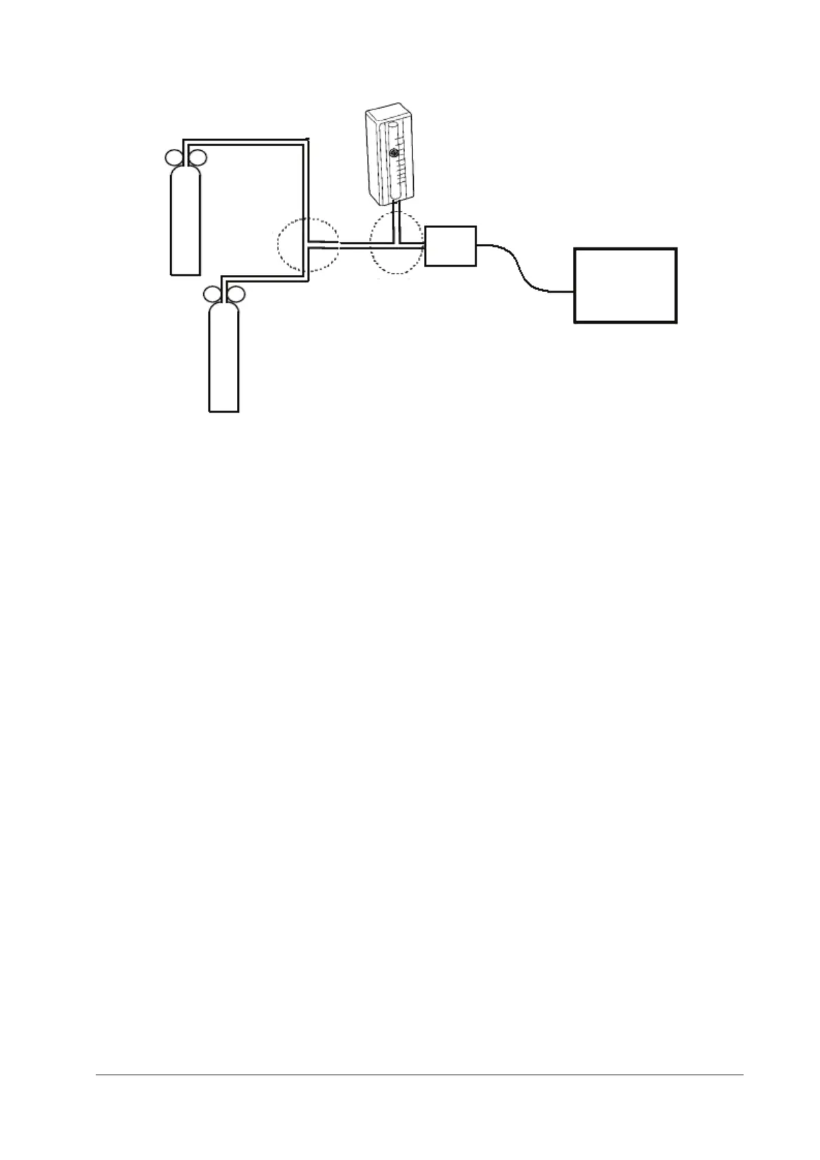
6. Separately turn on the relief valves of N
2
gas cylinder and CO
2
cylinder to ensure that only one gas cylinder is
connected to the T-shape connector at a time.
7. Separately adjust the relief valves to ensure a stable flow by maintaining the reading on the flowmeter at a value
between 2 L/min and 5 L/min.
8. Switch between the two cylinders connected to the T-shape connectors at intervals of 6–10s and check if the
displayed CO
2
value is within 45±2 mmHg.
5.4.8 Sidestream and Microstream CO
2
Modules Tests and Calibration
Refer to section 5.2.3 Sidestream and Microstream CO2 Modules Tests and Calibration.
5.4.9 PiCCO Test
5.4.9.1 Performance Test
Tools required:
Patient simulator: Medsim300B
PiCCO IBP test cable (P/N: 040-001300-00)
1. Connect the patient simulator, the PiCCO IBP test cable, and the PiCCO module.
2. Set the patient simulator to output 0 mmHg to the pArt channel and the pCVP channel.
3. In the pArt Setup menu, select pArt
Zero >>→Zero.
4. In the pCVP Setup menu, select pCVPZero >>→Zero.
5. Set the patient simulator to output static pressure 200 mmHg to the pArt channel and 20 mmHg to the pCVP
channel.
6. Check that the pArt value displayed on the monitor is within 200±4 mmHg, and pCVP value within 20±1 mmHg.
7. If the pArt error is beyond ±4 mmHg or pCVP error beyond ±1 mmHg, calibrate the PiCCO module. If the module
was calibrated with a dedicated reusable IBP sensor, check the calibration together with this IBP sensor.
Monitor
CO
2
gas
cylinder
Flowmeter
Relief
valve
Mainstream sensor
Relief valve
N2 gas cylinder
T-shape
connector
T-shape
connector