5-14
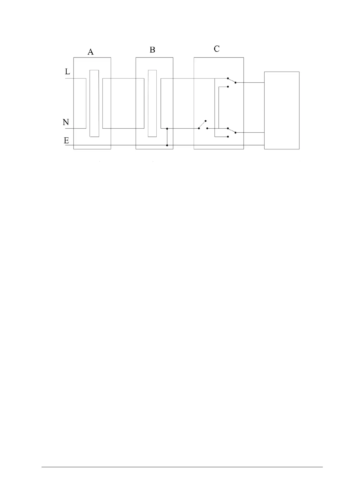
Device connection is shown in the following figure.
EUT
A : AC power supply (programmable, frequency control) B : Isolation transformer on leakage current test tooling C : Safety tester
Tools required:
Bio-Tek 601 Pro series safety analyzer
Isolation transformer
5.6.1 Enclosure Leakage Current Test
1. Connect the safety analyzer to a 264 V AC 60 Hz power supply.
2. Use the power cord to connect the EUT to the auxiliary power output connector of the safety analyzer.
3. Connect one end of the red lead to the "Red input terminal" of the safety analyzer, and clip the other end on the
metal foil attached on the surface of the outer enclosure of the EUT.
4. Power on the safety analyzer. Press 5-Enclosure leakage on the panel to access the interface for theenclosure
leakage current test.
5. Check that the enclosure leakage current is not greater than 100 µA in normal condition and is not greater than 300
µA in single fault condition.
5.6.2 Earth Leakage Current Test
1. Connect the safety analyzer to a 264 V AC 60 Hz power supply.
2. Connect the application part of the EUT to the RA terminal of the safety analyzer.
3. Use the power cord to connect the EUT to the auxiliary power output connector of the safety analyzer.
4. Power on the safety analyzer. Press 4-Earth leakage on the panel to access the interface for theearth leakage
current test.
5. Check that the earth leakage current is not greater than 300 µA in normal condition and is not greater than 1000 µA
in single fault condition.
5.6.3 Patient Leakage Current Test
1. Connect the safety analyzer to a 264 V AC 60 Hz power supply.
2. Connect the application part of the EUT to the RA terminal of the safety analyzer.