Appendix
13.2 Manual test procedures
5284 / 08/2023 en BENNING ST 755+ / ST 760+ 107
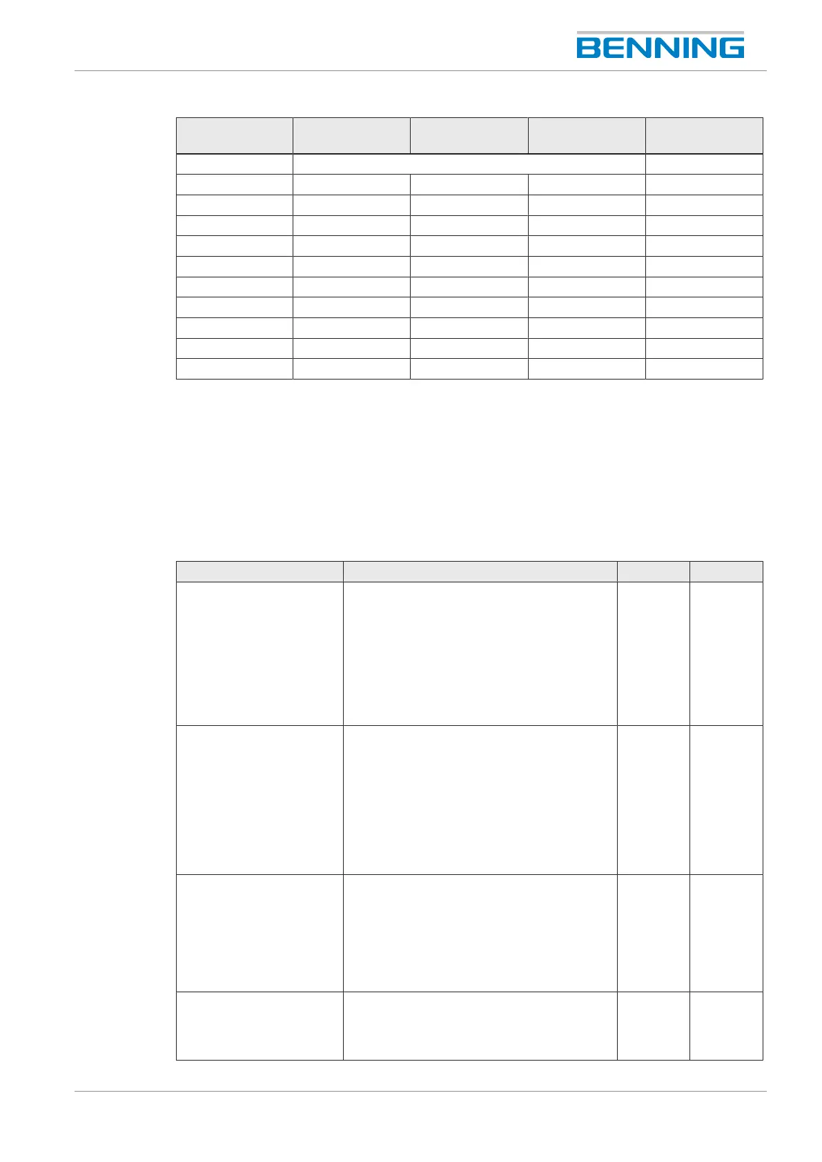
Test/
test no.
1 2 3 1
Protection class ClassI ClassII
Visual inspection X X X X
Connection test X X X X
R
PE
600mA X X X -
R
Insu-1
/ R
Insu‑IN
X X X X
R
Insu-2
X X X X
R
Insu-3
X X X X
I
Cont
X X X -
I
Contweld.
X X X X
Funct. X X X X
U
aweld.
X X X X
Table40: Overview of test procedures according to EN60974-4 (VDE0544‑4) for ClassI (1to 3)/
ClassII(1)
13.2 Manual test procedures
13.2.1 Manual test procedures according to EN50678
(VDE0701) and EN50699 (VDE0702)
Test ClassI ClassII ClassIII
Visual inspection for
visible defects:
• Connecting cables/
plug connections
• Housing, strain relief,
protection against
bending and kinking
etc.
X X X
Testing the protective
conductor with regard to:
Continuity between the
earthing contact of the
mains plug and accessible
conductive parts of the
device/ the device
connection
For cables with a rated current of ≤16.0A:
For cables up to 5m: ≤0.3Ω
For additional meters (up to 7.5m each),
0.1Ω is added to the limit up to a maximum
value of 1.0Ω.
For cables with higher rated currents, the
calculated ohmic resistance value shall
apply.
- -
Measuring the insulating
resistance
Generally: ≥1.0MΩ
For proving safe isolation: ≥2.0MΩ
For devices with heating elements:
≥0.3MΩ
For devices with heating elements and a
power of >3.5kW: ≥0.3MΩ
≥2MΩ ≥0.25MΩ
Measuring the protective
conductor current
≤3.5mA on conductive components with
PEconnection: 1mA/kW to max.10mA
for devices with heating elements and a
total power of more than 3.5kW
- -