Testing
9.5 Individual tests
5284 / 08/2023 en BENNING ST 755+ / ST 760+ 93
9.5.10 Testing the voltage of the welding circuit
Testing the voltage of the welding circuit [}page46] is intended to check the open-circuit
voltage for compliance with the specifications regarding the rated voltages of test samples
according to VDE0544‑4.
Requirements
• Approved safety measuring lines
• Please observe the requirements for measuring [}page71].
• The test sample is disconnected from the mains.
• Make sure that you are familiar with the procedure for manual [}page77] and automatic
[}page76] testing.
• The test sample has passed the insulating resistance test [}page80].
• Make sure that you know the necessary measuring points.
• The test sample is connected according to the connection diagram.
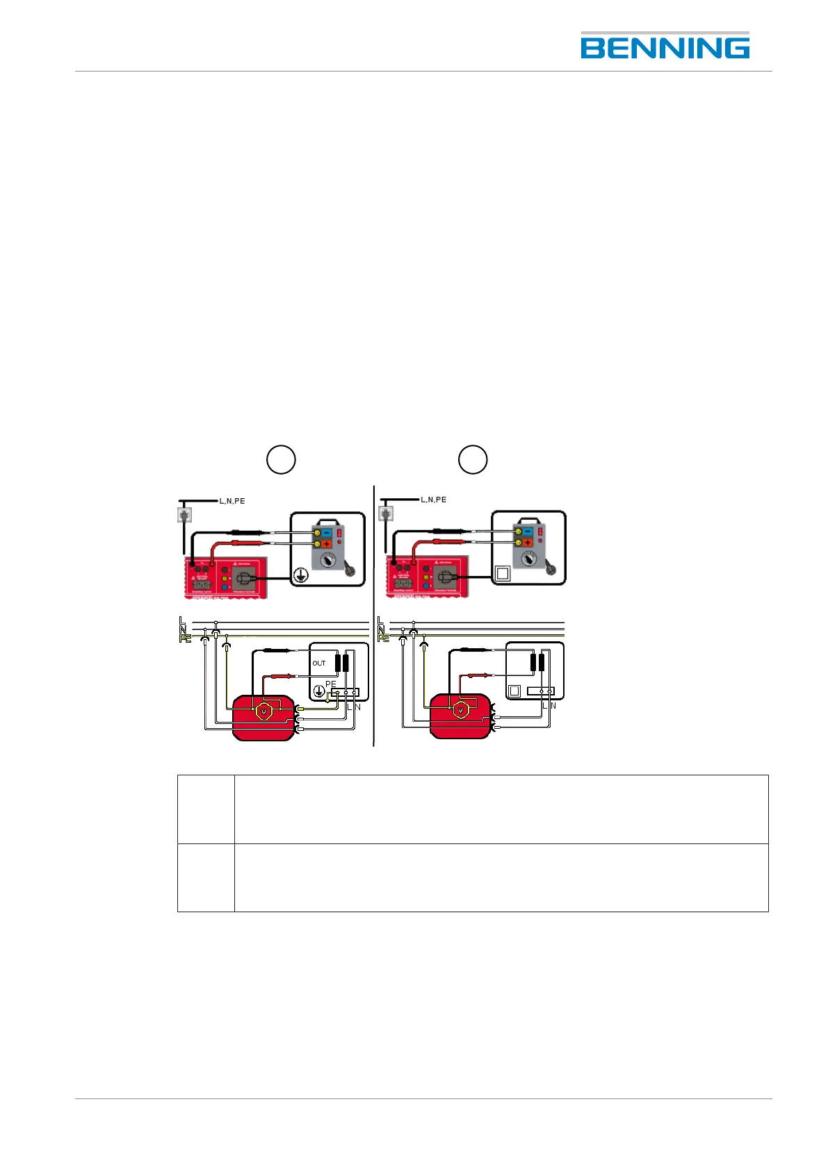
Figure25: Testing the voltage of the welding circuit (connection diagram, circuit diagram)
1 Voltage of the welding circuit (ClassI, U
a
)
The shock-proof plug of the test sample is plugged into the test socket of the device.
Use the test probes for measuring with correct polarity between both poles on the
secondary side of the test sample.
2 Voltage of the welding circuit (ClassII, U
a
)
The shock-proof plug of the test sample is plugged into the test socket of the device.
Use the test probes for measuring with correct polarity between both poles on the
secondary side of the test sample.