Appendix
13.4 Factory settings and measured values
5284 / 08/2023 en BENNING ST 755+ / ST 760+ 111
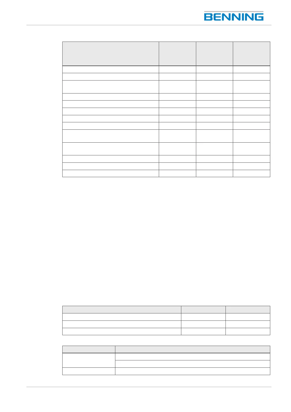
Test step EN50678
(VDE0701),
EN50699
(VDE0702)
EN62353
(VDE0751‑1)
EN60974‑4
(VDE0544‑4)
Visual inspection X X X
Protective conductor resistance X X X
Insulating resistance X X
(optional)
X
Protective conductor current X X -
Contact current X X X
Patient leakage current - X -
Device leakage current - X -
Open-circuit voltage - - X
Safe isolation from power supply circuit
(SELV/ PELV)
X - -
Effectiveness of further protective
equipment
X X X
Inspection of markings X X X
Functional test X X X
Analysis, evaluation, documentation X X X
Table45: Overview of test steps
For testing, the following provisions, regulations and standards shall be authoritative:
• EN50678 (VDE0701)
• EN50699 (VDE0702)
• EN62353 (VDE0751-1)
• EN60974-4 (VDE0544-4)
• BetrSichV (German health and safety at work regulation)
• TRBS1201 (German technical guideline for operational safety)
• TRBS1203 (German technical guideline for operational safety)
• DGUVRegulation3 (German accident prevention regulation)
13.4 Factory settings and measured values
13.4.1 Factory settings and measured values– Protective
conductor resistance tests
Test Value Unit
R
PE
VDE0701/0702 0.3 Ω
R
PE
VDE0751-1 0.3 Ω
R
PE
VDE0544-4 0.3 Ω
Table46: Factory settings of the limits for protective conductor resistance tests (conductor 5m, 1.5mm
2
)
Parameter Value
Testing current 600mA‑AC ±30% at 0… 5Ω
10A‑AC ±30% at 0Ω
Testing voltage U
0
approx. 8V‑AC