Testing
9.5 Individual tests
5284 / 08/2023 en BENNING ST 755+ / ST 760+ 91
9.5.8 Cable continuity test
The cable continuity test [}page46] is intended to measure the line resistance.
Requirements
• Approved safety measuring lines
• Please observe the requirements for measuring [}page71].
• The test sample is disconnected from the mains.
• Make sure that you are familiar with the procedure for manual [}page77] and automatic
[}page76] testing.
• Make sure that you know the necessary measuring points.
• The test sample is connected according to the connection diagram.
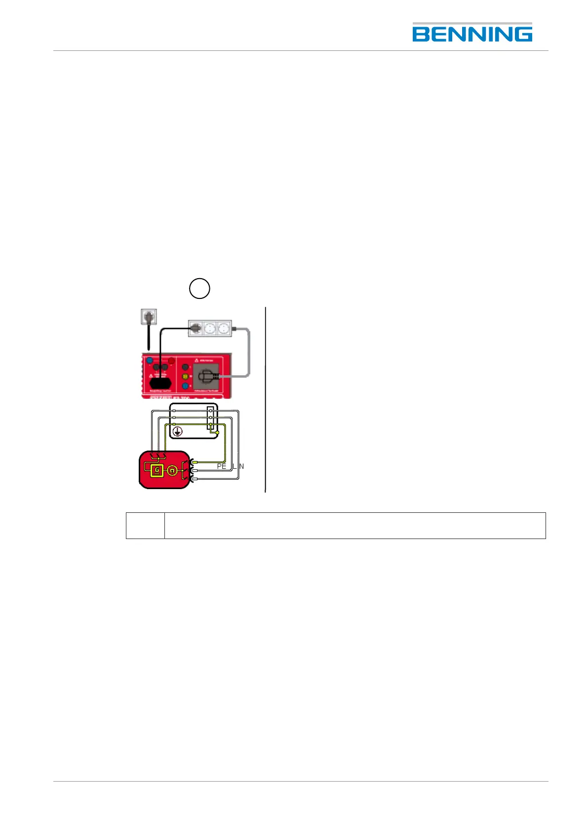
Figure23: Cable continuity test (example: multiple socket, connection diagram, circuit diagram)
1 Cable continuity test (ClassI, cable)
Connection between test socket, test sample and IECsocket of the device.
Procedure
1. If necessary, adjust the following limits:
– Line length [m]
– Line cross-section [mm²]
– Number of conductors
– Rline per conductor [Ω]
2. Start the test.
The measurement is made continuously, so you have enough time to carry out the test. The
device measures the line resistance of the conductors (L,N,PE) and all conductors in
series.