9.5 Individual tests
Testing
5284 / 08/2023 enBENNING ST 755+ / ST 760+90
9.5.7 Functional test
The functional test [}page45] is intended for the final verification of electrical safety.
Requirements
• Approved safety measuring lines
• Please observe the requirements for measuring [}page71].
• The test sample is disconnected from the mains.
• Make sure that you are familiar with the procedure for manual [}page77] and automatic
[}page76] testing.
• Make sure that you know the necessary measuring points.
• The test sample has passed the safety test.
• The test sample is connected according to the connection diagram.
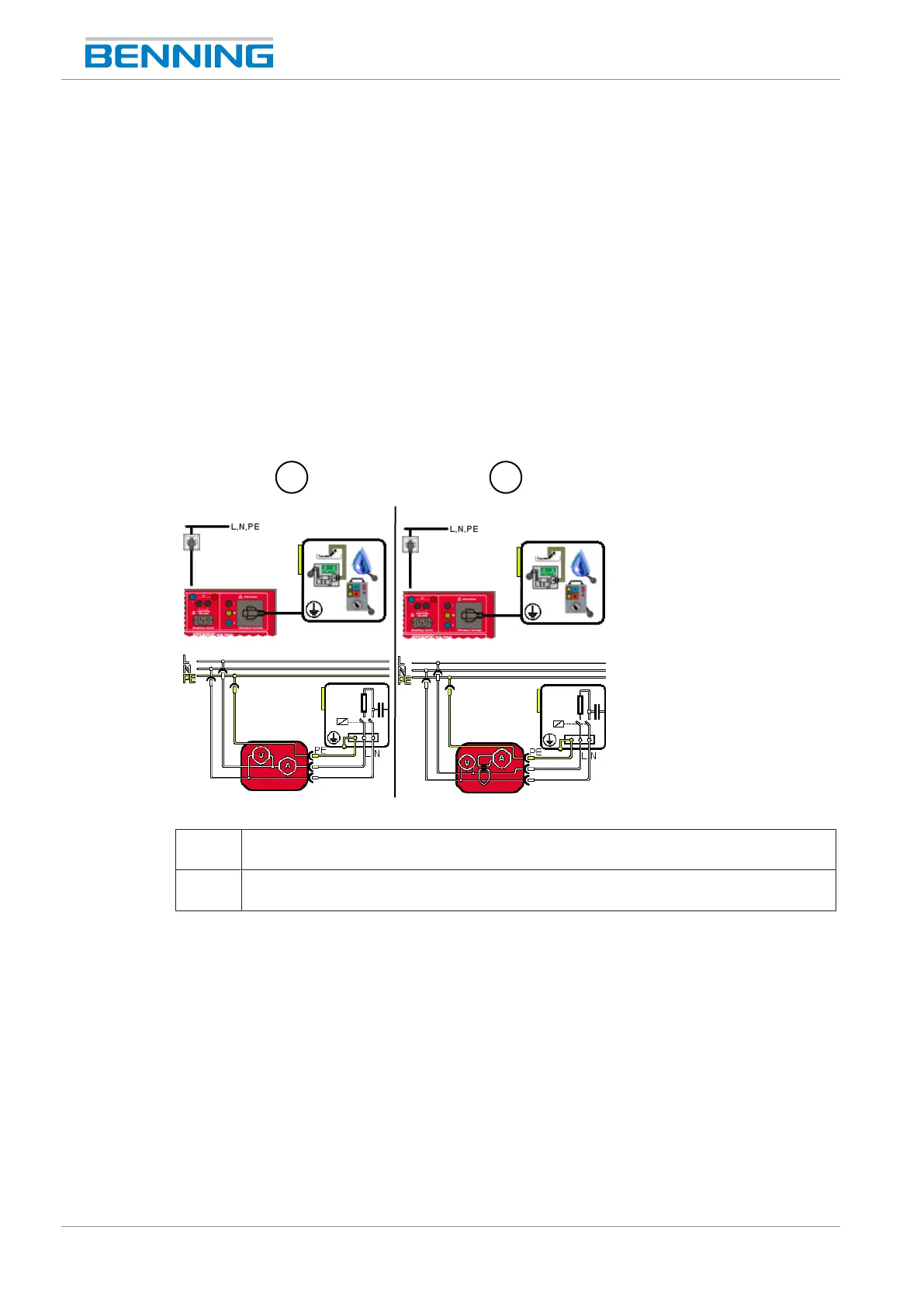
Figure22: Functional test (connection diagram, circuit diagram)
1 Direct current measuring method (ClassI, function)
The shock-proof plug of the test sample is plugged into the test socket of the device.
2 Differential current measuring method (ClassI, function)
The shock-proof plug of the test sample is plugged into the test socket of the device.
Procedure
1. Start the test.
2. When testing a test sample of protection classII, use the test probe to scan all accessible
conductive components of the test sample for contact current testing. For leakage current
measurement, scan all active accessible and conductive components that are connected to
the housing.
Please observe inductive and capacitive circuits.
3. Change the polarity of the mains voltage at the test socket [}page31].
4. Use the test probe again to scan all components.
Test the test sample in all switch positions (test sample functions), if available.