Testing
9.5 Individual tests
5284 / 08/2023 en BENNING ST 755+ / ST 760+ 95
2 Contact current of the welding circuit (ClassII, I
Cont
)
The shock-proof plug of the test sample is plugged into the test socket of the device.
Use the test probe for measuring on both poles of the secondary side of the test
sample.
Procedure
1. Start the test.
2. Use the test probe for measuring on the poles of the secondary side.
3. Change the polarity of the mains voltage at the test socket.
4. Use the test probe again for measuring on the poles of the secondary side.
5. Check the measured value for compliance with the technical data of the test sample.
9.5.12 Testing of PRCDs
The testing of residual current protection devices [}page47] is intended to check the
functionality of portable residual current protection devices (PRCD).
Menu
“Mainmenu> VDE0701,VDE0702> Devices with PE (ClassI)”
Requirements
• Approved safety measuring lines
• Please observe the requirements for measuring [}page71].
• The test sample is disconnected from the mains.
• Make sure that you are familiar with the procedure for manual [}page77] and automatic
[}page76] testing.
• Make sure that you know the necessary measuring points.
• The test sample is connected according to the connection diagram.
• Please observe the operating manual and the technical data of the test sample.
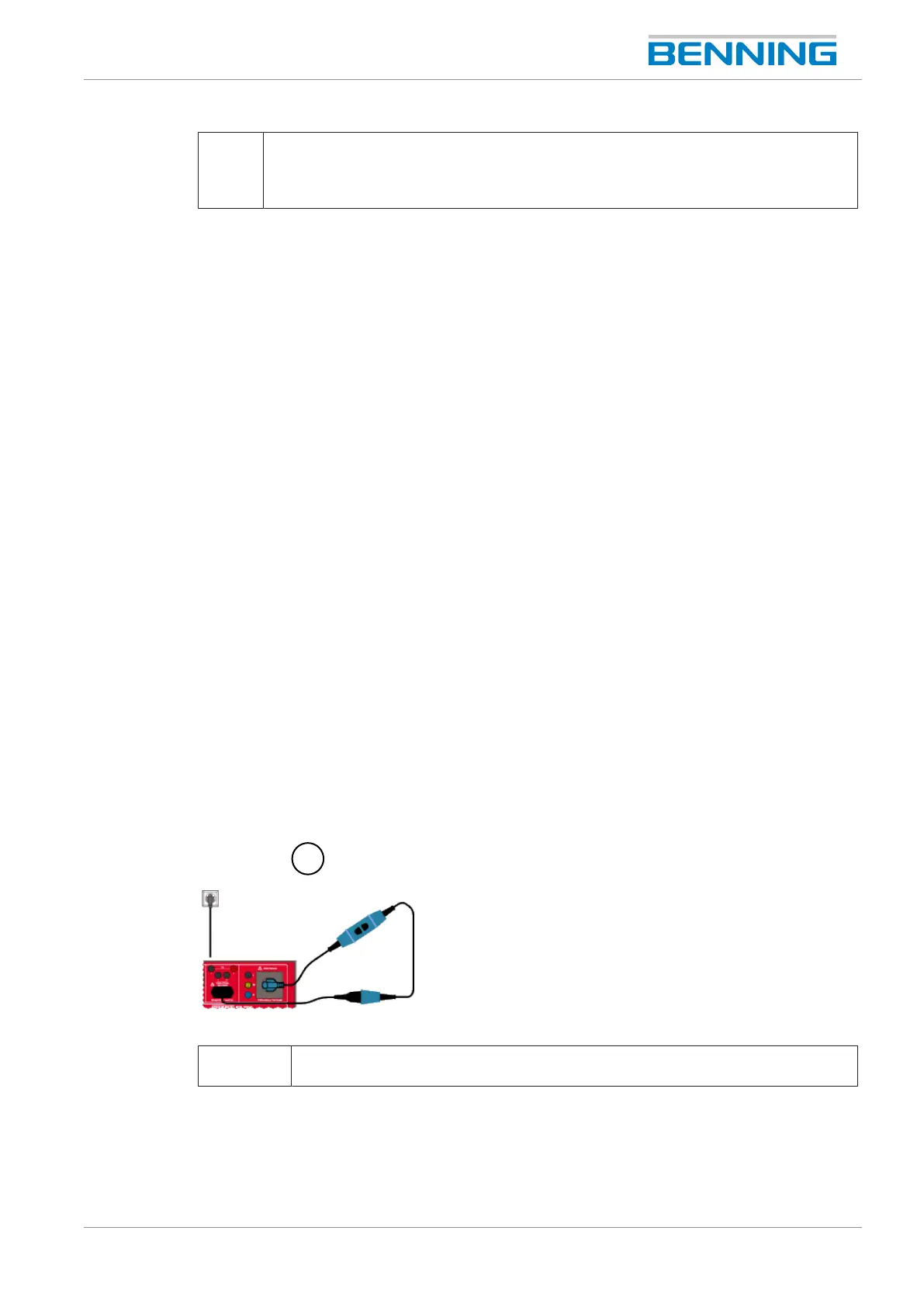
Figure27: Testing of PRCDs (connection diagram)
1 Direct current measuring method (ClassI, PRCD)
Connection between test socket, test sample and IECsocket of the device.
Procedure
1. Start the test.
2. Check the measured value for compliance with the technical data of the test sample.