9.5 Individual tests
Testing
5284 / 08/2023 enBENNING ST 755+ / ST 760+80
3 Stationary test sample (ClassI, R
PE
)
Establish a connection between the PEjack of the device and the protective conductor
connection point of the test sample. Use the test probe for measuring on all accessible
conductive components of the test sample that are connected to the protective
conductor.
Procedure
1. Apply the test probe to the first measuring point and start the test.
2. During the measurement, move all movable individual parts of the protective conductor
section.
3. Observe the measured values on the display. The highest measured value will be saved.
4. When the acoustic signal is emitted, apply the test probe to the next measuring point.
Repeat the measuring steps2to4 at all other measuring points.
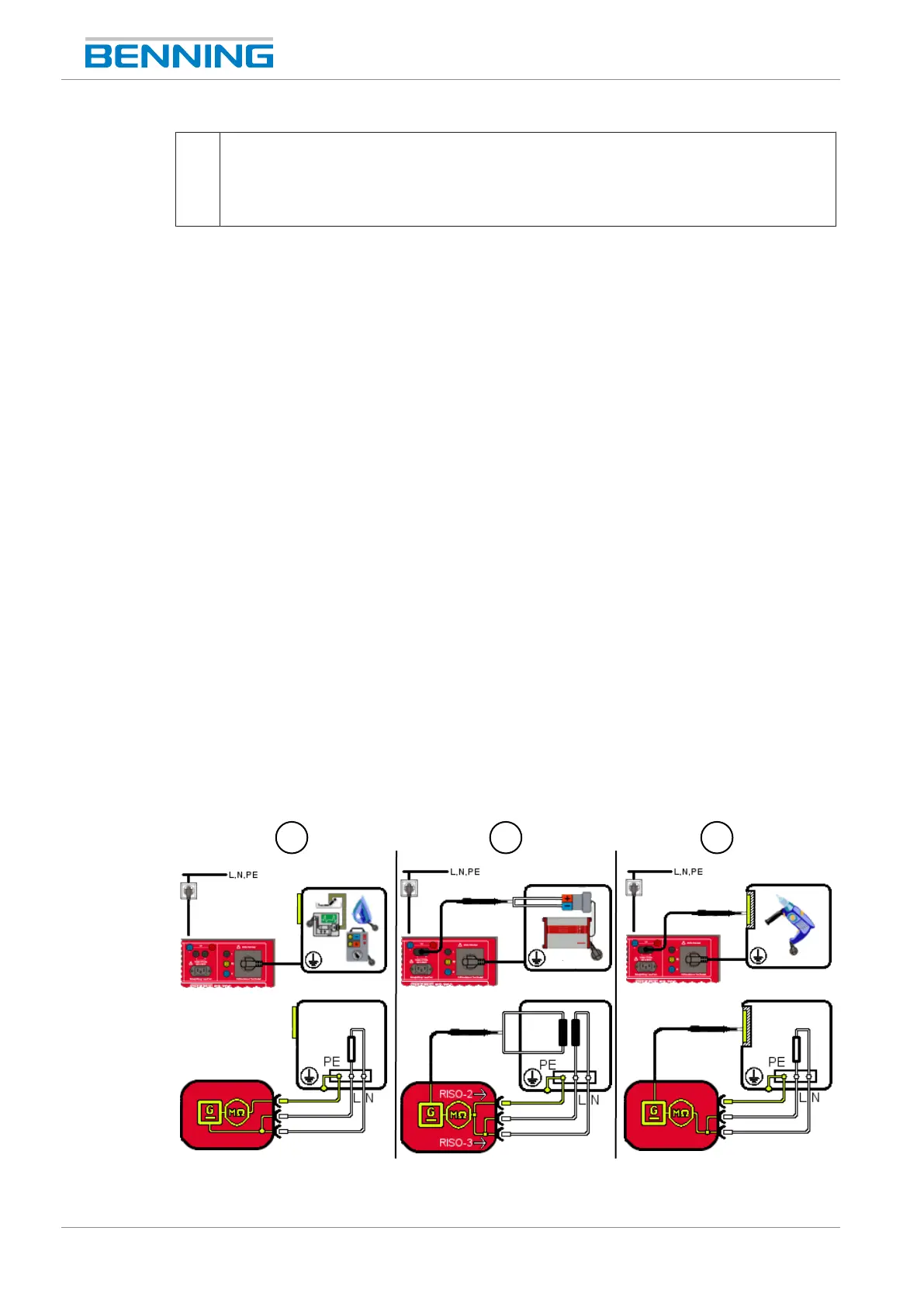
9.5.2 Testing the insulating resistance
The insulating resistance test [}page43] is intended to check the insulation of the test sample
for a sufficiently high resistance. A high insulating resistance ensures that no fault currents can
flow off if all sections of the test sample have been covered by the test.
Requirements
• Approved safety measuring lines
• Please observe the requirements for measuring [}page71].
• The test sample is disconnected from the mains.
• Make sure that you are familiar with the procedure for manual [}page77] and automatic
[}page76] testing.
• The test sample has passed the protective conductor resistance test [}page79].
• Make sure that you know the necessary measuring points.
• The test sample is connected according to the connection diagram.
Figure13: Testing the insulating resistance, ClassI (connection diagram exemplary for VDE0701 and
VDE0702, circuit diagram)