Device description
5.1 Device structure
5284 / 08/2023 en BENNING ST 755+ / ST 760+ 21
5 Device description
5.1
Device structure
The device comes in a closable device case. The cover of the device case can be removed via
two cotter pins in the hinges.
1
2 3 4
5 6
7
8
9
11
12
13
14
12
13
11
14 15
16
10
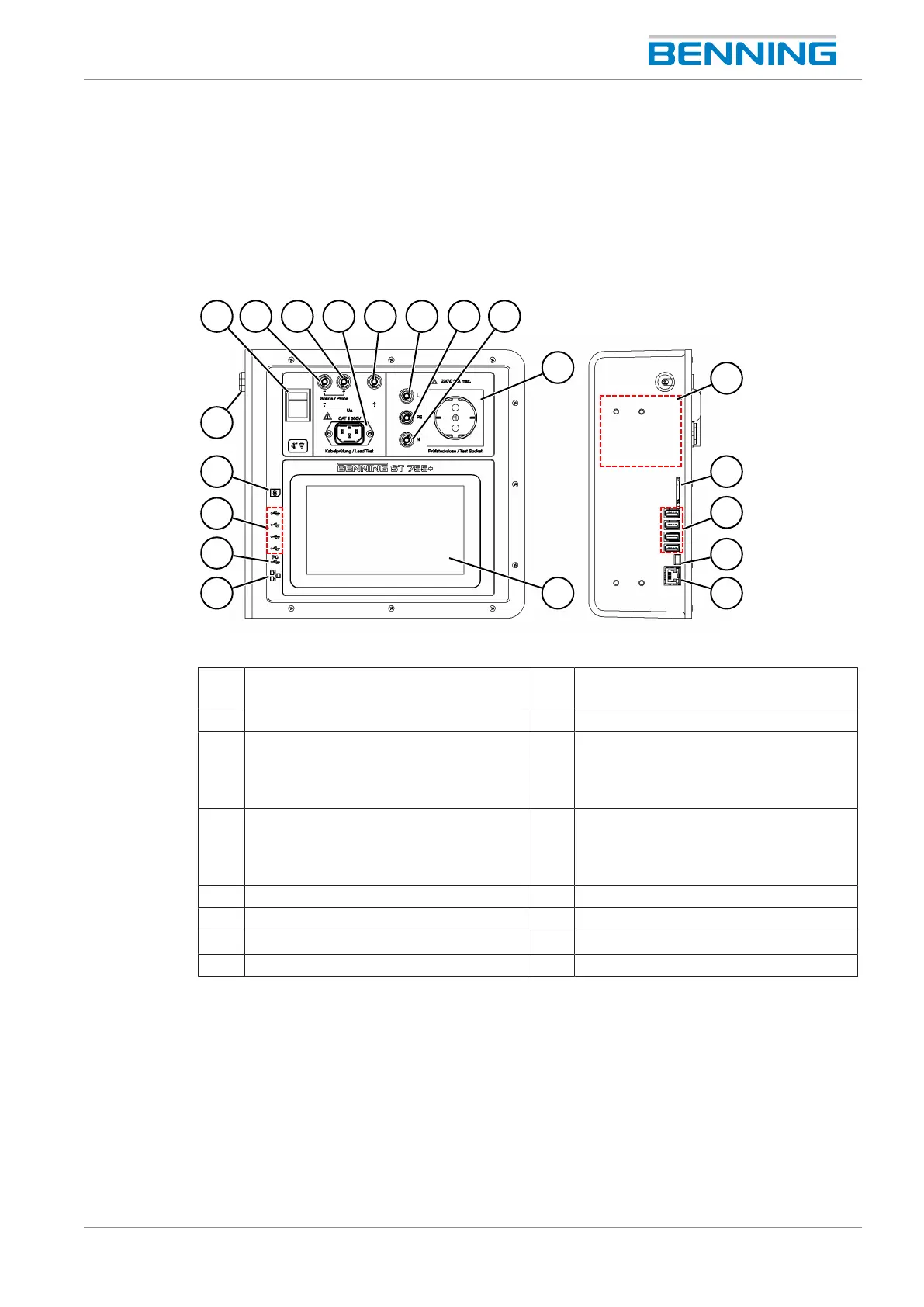
Figure1: BENNINGST755+/ BENNINGST760+ device structure
1 Mains switch (O–I) 2 Black measuring jack "-" for test probe
and open-circuit voltage (U
a
)
3 Black measuring jack "+" for test probe 4 IECsocket for cable test
5 Red measuring jack "+" for open-circuit
voltage (U
a
)
6 Black "L" jack (is connected to the "L"
of the test socket, connection is
disconnected when mains voltage is
applied to the test socket)
7 Green-yellow calibration jack “PE” 8 Blue “N" jack (is connected to the “N" of
the test socket, connection is
disconnected when mains voltage is
applied to the test socket)
9 Test socket 10 Type plate
11 SDmemory slot 12 USB‑A interfaces
13 USB Mini-B interface 14 Ethernet interface
15 7" touch display 16 Mains connection cable