13.4 Factory settings and measured values
Appendix
5284 / 08/2023 enBENNING ST 755+ / ST 760+116
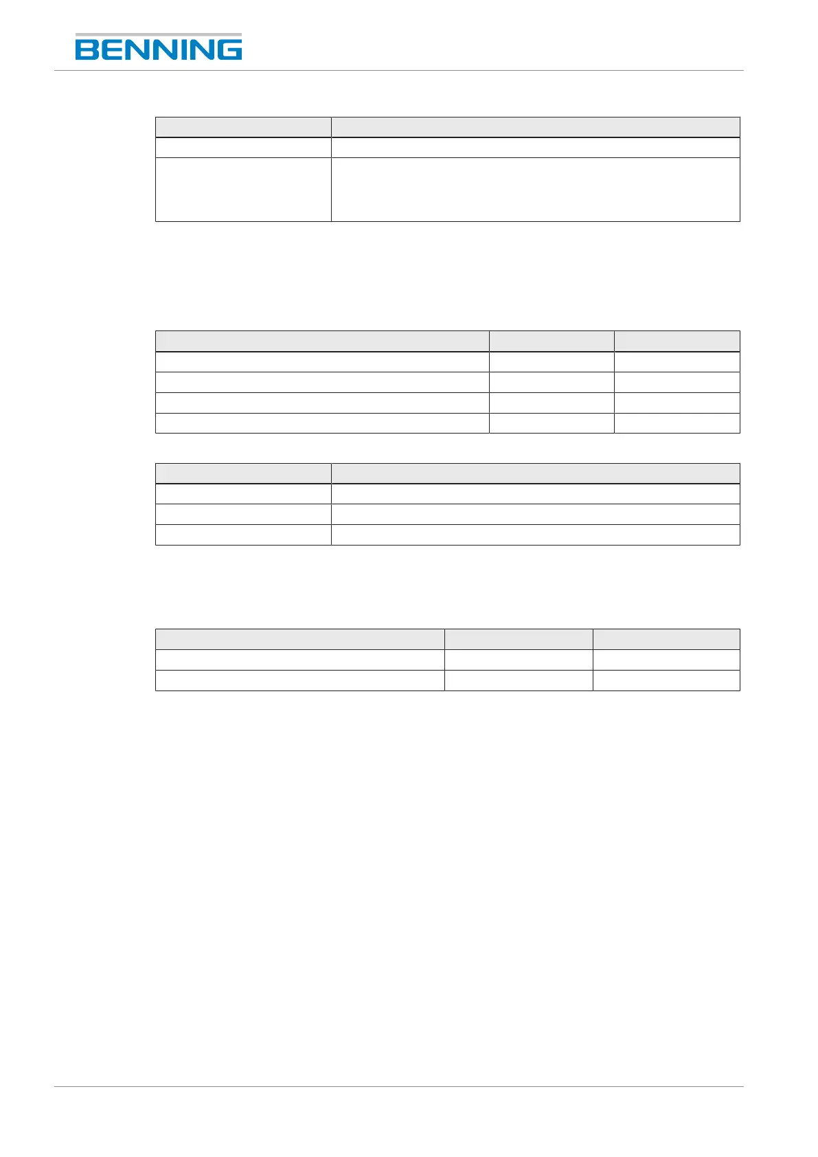
Parameter Value
Types of current Sinusoidal, DC+/-, half-wave 0° and 180°
Accuracy • Tripping fault current: 0… 10% (I
n
, 5xI
n
)
• Non-tripping fault current: -10... 0% (I
n
/2)
• Tripping time: ±10% of the maximum admissible tripping time
Table64: Measured values according to measuring specifications– PRCD
13.4.8 Factory settings and measured values– Voltage of the
welding circuit test
Parameter Value Unit
U
a
VDE0701/0702, max. output voltage 25 V
U
a
weld. VDE0544-4, max. output voltage AC 80 V
U
a
weld. VDE0544-4, max. output voltage DC 80 V
U
a
weld. VDE0544-4, max. peak value 113 V
Table65: Factory settings of the limits for voltage of the welding circuit test
Parameter Value
Measuring range 10... 200V‑DC, 140V‑AC
Resolution 0.1V
Accuracy ±2.5% of the final measuring range value
Table66: Measured values according to measuring specifications– Voltage of the welding circuit test
13.4.9 Factory settings and measured values– Times
Parameter Value Unit
Test times for individual tests 5 s
Default delay time (mains pole reversal) 0 ms
Table67: Factory settings of the limits for times