Testing
9.5 Individual tests
5284 / 08/2023 en BENNING ST 755+ / ST 760+ 79
9.5 Individual tests
This chapter describes the procedure for individual tests in the automatic and manual testing
modes.
9.5.1 Testing the protective conductor resistance
Testing the protective conductor resistance [}page42] is intended to check a test sample for
proper and safe connection to all accessible conductive parts that are connected to the
protective connector.
Requirements
• Approved safety measuring lines
• Please observe the requirements for measuring [}page71].
• The test sample is disconnected from the mains.
• Make sure that you are familiar with the procedure for manual [}page77] and automatic
[}page76] testing.
• Make sure that you know the necessary measuring points.
• The test sample is connected according to the connection diagram.
• Please observe the operating manual and the technical data of the test sample.
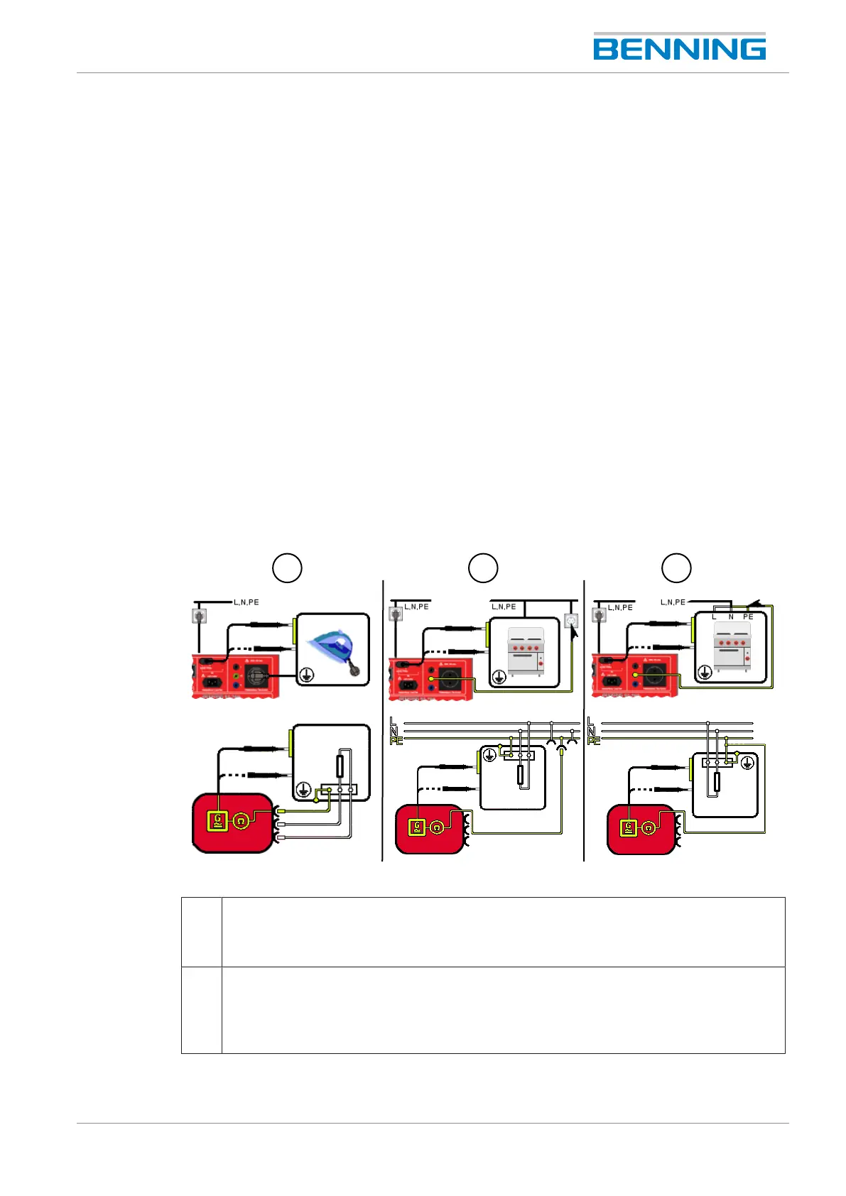
Figure12: Testing the protective conductor resistance (connection diagram exemplary for VDE0701 and
VDE0702, circuit diagram)
1 Portable test sample (ClassI, R
PE
)
The shock-proof plug of the test sample is plugged into the test socket of the device.
Use the test probe for measuring on all accessible conductive components of the test
sample that are connected to the protective conductor.
2 Stationary test sample (ClassI, R
PE
)
Establish a connection between a parallel PEsection (e.g. a shock-proof socket in the
same circuit) and the PEjack of the device. Use the test probe for measuring on all
accessible conductive components of the test sample that are connected to the
protective conductor.