9.5 Individual tests
Testing
5284 / 08/2023 enBENNING ST 755+ / ST 760+82
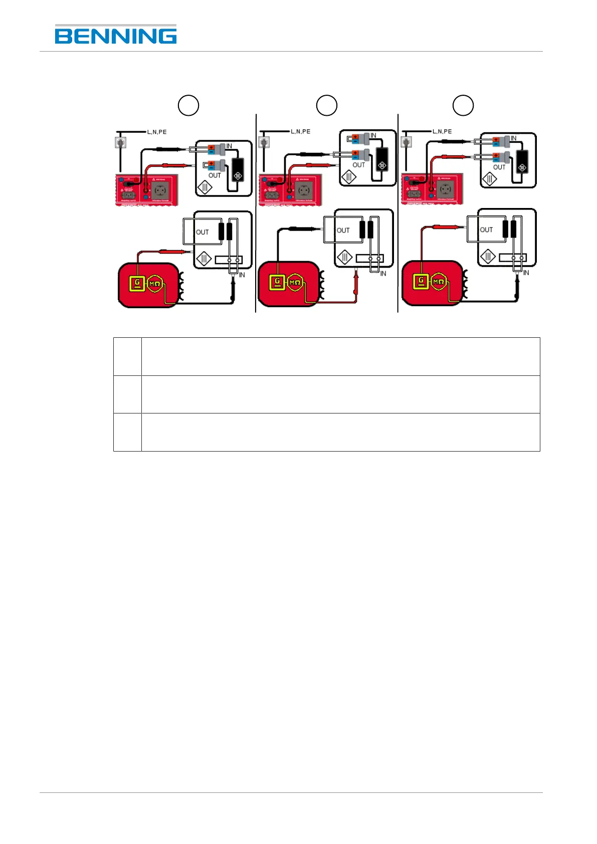
Figure15: Testing the insulating resistance, ClassIII (connection diagram exemplary for VDE0701 and
VDE0702, circuit diagram)
7 Input to test body (ClassIII, R
Insu-1
)
Use the probe tip (PEjack) for measuring on the body of the test sample and use the
test probe for measuring on the input of the test sample.
8 Output to test body (ClassIII, R
Insu-2
)
Use the probe tip (PEjack) for measuring on the body of the test sample and use the
test probe for measuring on the output of the test sample.
9 Output to test body (ClassIII, R
Insu-3
)
Use the probe tip (PEjack) for measuring on the output of the test sample and use the
test probe for measuring on the input of the test sample.
Procedure
1. Start the individual test.
2. Carry out the first measurement. If there are several measuring points, pause the
measurement. To do this, tap the “Pause”button.
3. Apply the test probe/ probe tip to the next measuring point.
4. Continue the measurement. To do this, tap the “Next”button.