Configuration
8.7 Zero balance, cable and probe calibration
5284 / 08/2023 en BENNING ST 755+ / ST 760+ 69
8.7 Zero balance, cable and probe calibration
Calibrate the device during initial commissioning using the internal calibration.
During the probe calibration, the transition resistances in the device including the cable of the
connected probe are calibrated. You can change between a probe of 2m and a probe of 5m
without having to calibrate again.
If you use a 1-pin probe, place a bridge between the “Sonde/Probe” jacks “+” and “-”.
Requirements
• Please observe the requirements for measuring [}page71].
• Approved safety measuring lines
• The test sample is disconnected from the mains.
• The test sample is connected according to the connection diagram.
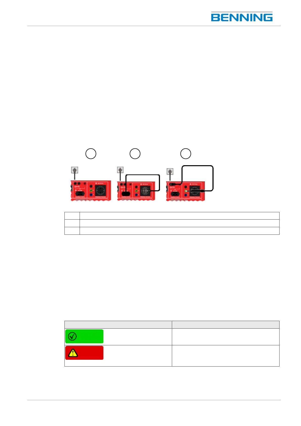
Figure10: Balance/ calibration
1 ZERObalance
2 Cable calibration
3 Probe calibration
Menu
“Settings> Balance/calibration”
Procedure
1. Start the desired balance/ calibration.
2. Follow the instructions on the display.
Result
Control display Description
The calibration/ balance was successful.
The calibration/ balance has failed.
Check the plug connections as well as the
steps you have taken and start the test again.