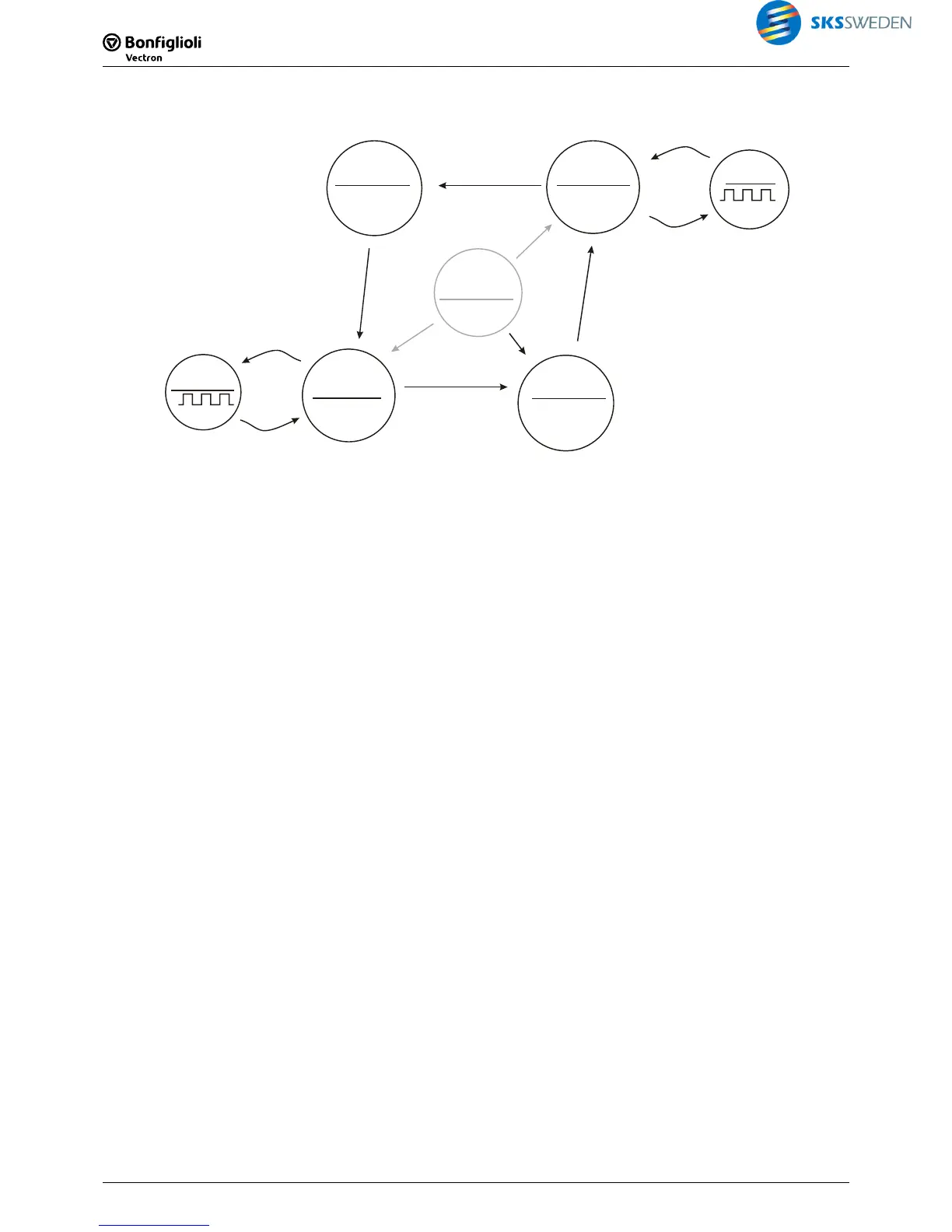
With the assignment of the digital ACU signals, the following diagram is obtained:
S2IND=1
S5IND=1
S3IND=1
EM-S1OUTD
S1OUTD=0
=1
Start CW
068
S4IND=1
S5IND=0
S2IND=1
S4IND=1
No
initiator
S3IND=1
S3OUTD=1
=0
Start CW
068
S1OUTD=1
=0
Start CCW
069
S3OUTD=0
=1
Start CCW
069
MFO1D
Travel
up
Position
top
Position
bottom
Travel
down
Warning
signal
Initializing
Warning
signal
Solution:
For assignment of the ACU signals and the input buffer of the function table, the following pa-
rameterization is required:
2002:
FT-Input Buffer 1362, Index 2 : "71 – S2IND"
2003:
FT-Input Buffer 1362, Index 3 : "72 – S3IND"
2004:
FT-Input Buffer 1362, Index 4 : "73 – S4IND"
2005:
FT-Input Buffer 1362, Index 5 : "74 – S5IND"
2006:
FT-Input Buffer 1362, Index 6 : "274 – S5IND inverted" (*)
(*): Parameterization deviating from factory settings.
For assignment of the ACU signals and the output buffer of the function table, the following
parameterization is required:
Operation mode digital output 1
530
2401 - FT-Output buffer 1
Operation mode digital output 3
532
2402 - FT-Output buffer 2
Op. Mode EM-S1OUTD 533
2404 - FT-Output buffer 4
MFO1:
Operation mode 550
1 - Digital output
MFO1:
Digital Operation 554
2403 - FT-Output buffer 3
Start Clockwise 068
2410 - FT-Output buffer 10
Start Anticlockwise 069
2411 - FT-Output buffer 11
To enable easy checking of the transition "Top Position"
Æ "Down", the inverted signal of signal
S5IND in the input buffer is assigned. For easier parameterization, the names of the states used
so far will be replaced by numerical values.
 Loading...


