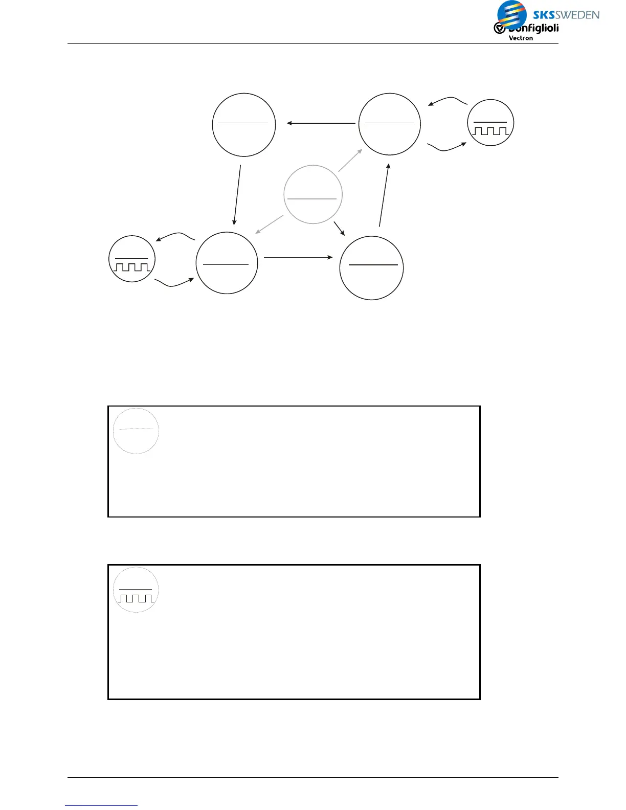
The following diagram is obtained for the signals of the function table:
4
2002=1
2005=1
5
2003=1
2404
3
2
2401=1
2411=0
5a
2401=0
2410=1
2402=0
2411=1
2402 = 1
2410 = 0
2004=1
2006=1
(”2005=0”)
1
2002=1
2004=1
No
Initiator
2403
3a
2003=1
In the first step, the states and transitions are translated into instructions.
Setting state outputs:
The easiest way to set a digital signal (independent of one or several input signals) is using a
Boolean operation. In this application, an OR instruction is used and an input is set to TRUE. In
this way,
FT target output 1 1350 is set to TRUE (=1) and FT target output 2 1351 is set to
FALSE (=0).
2
2402 =0
2411 =1
Æ
FT-Instruction 1343
2 – OR
FT input 1 1344
6 – TRUE
FT input 2 1345
7 – FALSE
FT input 3 1346
7 – FALSE
FT input 4 1347
7 – FALSE
FT-Parameter 1 1348
0
FT-Parameter 2 1349
0
FT target output 1 1350
2411 FT-Output buffer 11
FT target output 2 1351
2402 FT-Output buffer 2
For states 3 to 5, instructions can be created in the same way.
Clock generator (state 3a)
2403
3a
Æ
FT instruction 1343
80 – Clock generator
FT input 1 1344
2003 - Input buffer 3
FT input 2 1345
7 – FALSE
FT input 3 1346
7 – FALSE
FT input 4 1347
7 – FALSE
FT-Parameter 1 1348
100
FT-Parameter 2 1349
100
FT-Target Output 1
1350
0
FT-Target Output 2
1351 0
The clock generator of state 5a is created in the same way as 3a.
 Loading...


