- 39 -
Adding Fixtures to a Project
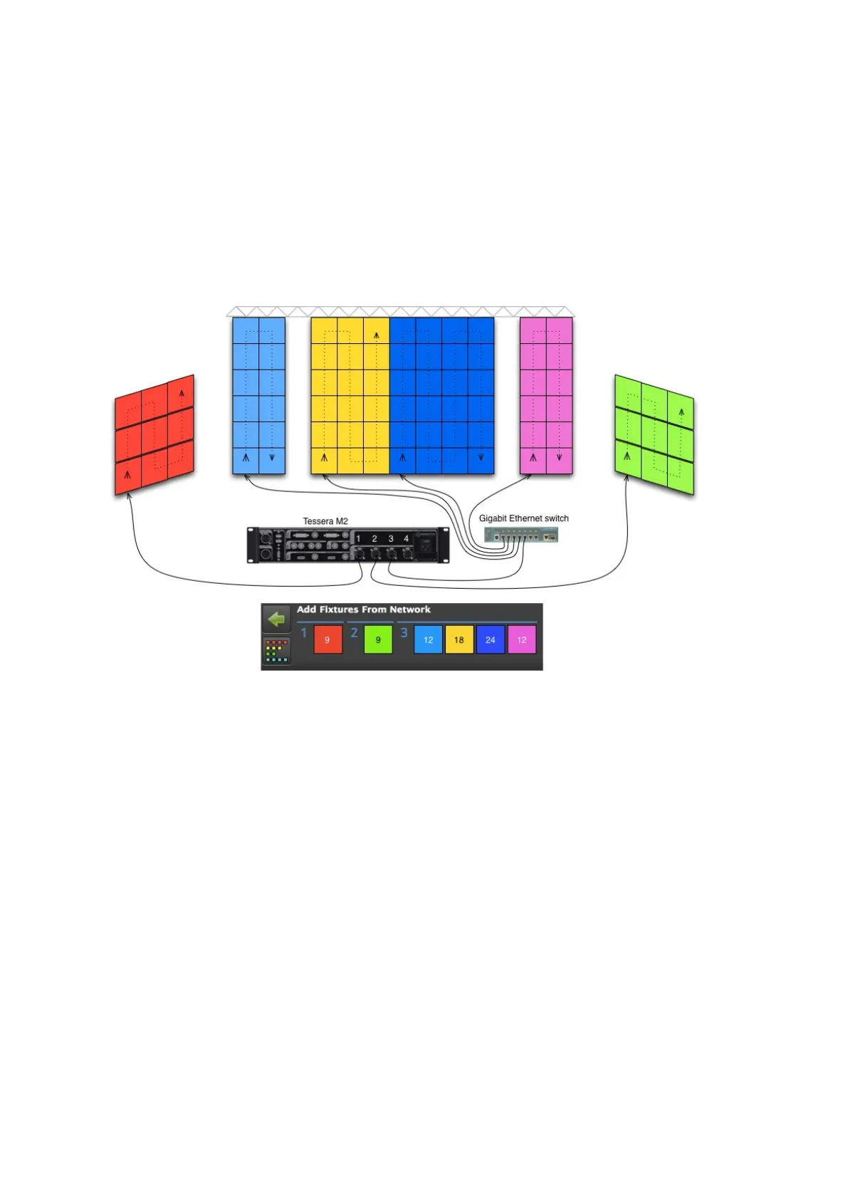
The diagram below shows a typical system setup with some strings connected directly from
the processor and some via a network switch. Each differently coloured group of panels
represents one of the strings in the screenshot in the previous section. The red and green
strings are connected directly to output ports 1 and 2 of the processor. The light blue,
yellow, dark blue and purple strings are connected to port 3 via a network switch.
Figure 5-4. An example of a Tessera system topology.
The topology (cabling) of a Tessera system is very simple. The fixtures just need to be
connected to the processor either directly or via a switch. Once connected, a group of
fixtures in an unbroken line becomes a string. Each string is represented by a different colour
in the user interface and can be placed on the canvas as desired.
There are two ways to add fixtures to your project . If you already have fixtures connected,
you can add these directly to your canvas. Alternatively, you can add offline fixtures to your
canvas, that are then associated with fixtures on the network at a later stage (see Section -
Associating Fixtures).