3-119
Confidential
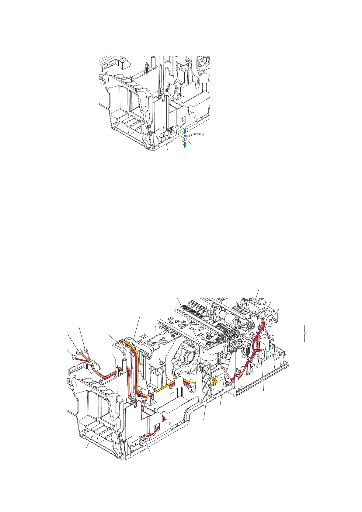
(8) Remove the ink cartridge cover switch from the front right side of the lower cover.
Assembling Notes:
• When mounting the engine unit on the lower cover, be careful not to crush the harnesses
between the engine unit and the cover. Mount the engine unit parallel to the lower cover and
tighten the screws securely.
• After mounting the engine unit, route the harnesses through the cable guides on the right and
left ends of the lower cover. (See the figure below and the next page.)
• If you replace the flushing box (without replacing the main PCB), you also need to replace
the ink absorber box (see Section 3.9.15) and reset both the flushing and purge counts as
specified in Chapter 4, Section 4.4.
• If you replace the engine unit, make adjustments specified in Chapter 4, Section 4.1.
• The DX chassis (Section 3.9.16) is positioned with reference to the engine unit. If the engine
unit is removed and mounted, therefore, it is necessary to position the DX chassis again (see
page 3-116).
(3_089)
(Front)
Lower cover
Ink cartridge cover switch
(3_086)
Carriage motor
Carriage motor
harness
ASF motor
harness
Purge cam
switch harness
ASF encoder
harness
Ink cartridge
cover switch
harness
Lower cover
Ink cartridge cover switch
Ferrite core of
carriage motor harness
(Right)
Purge cam switch harness
Ferrite core of
ASF motor harness
ASF encoder
harness
ASF motor
harness
ASF
motor/
encoder
harness
ASF encoder disk
ASF motor/
encoder PCB
ASF motor
 Loading...