BRP-Rotax
INSTALLATION MANUAL
Fusebox Regula-
tor A
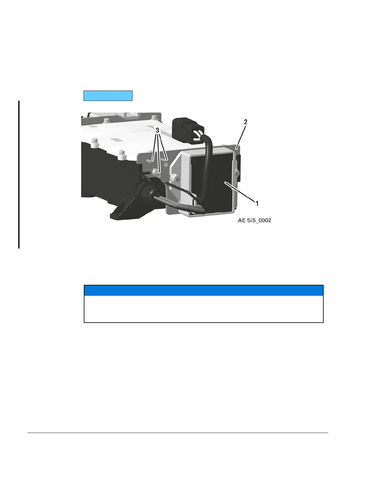
The regulator plate A needs to be connected with the EMS Ground (ring terminals on the
(engine-) wiring harness). The stud has M4 threads suitable for ring terminals according to
DIN 46225 or MS25036– 149 (size #8) (tightening torque: 1.2 Nm / 11 in lb). The ring ter-
minals need to be evenly spread onto the three available studs.
916 i TYPE C24
Figure 3.13: Fusebox -Regulator A
1
Regulator
2
Regulator plate A
3 Ground studs
NOTICE
A connection between regulator plate A and airframe ground should only be
done during supply of the EMS System by an external power source (e.g. during
engine start).
24–00–00
Page 14
December 01 2023
Effectivity: 916 i A / C24
Edition 0/Rev. 1

 Loading...


