EasyManuals Logo

BRP ROTAX 916 i A Series Installation Manual

BRP ROTAX 916 i A Series
223 pages
To Next Page IconTo Next Page
To Previous Page IconTo Previous Page
Page #68 background imageLoading...
Page #68 background image
BRP-Rotax
INSTALLATION MANUAL
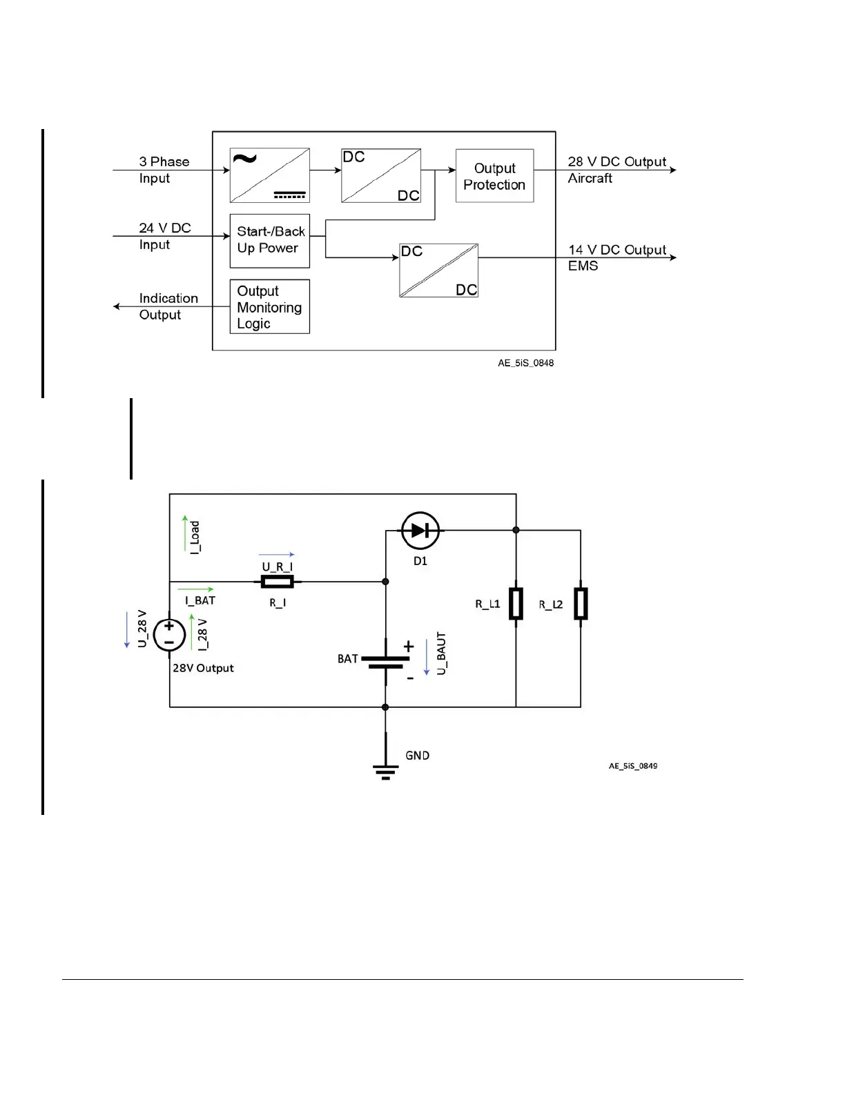
Figure 3.20: Schematic AC-DC Converter
Concept for limiting the charging current:
In order to limit the charging current, a series resistor can be used. In following Figure this
resistor is called R_I. R_L1 and R_L2 are symbolically shown as load (L= Load) of the 28
V output and define the current flow I_Load.
Figure 3.21: Simple Charging Circuit
24–00–00
Page 24
December 01 2023
Effectivity: 916 i A / C24
Edition 0/Rev. 1

Table of Contents

Other manuals for BRP ROTAX 916 i A Series

Questions and Answers:

Question and Answer IconNeed help?

Do you have a question about the BRP ROTAX 916 i A Series and is the answer not in the manual?

BRP ROTAX 916 i A Series Specifications

General IconGeneral
BrandBRP
ModelROTAX 916 i A Series
CategoryEngine
LanguageEnglish

Related product manuals