3-26 2007 Buell Lightning: Engine
HOME
NOTES
● Anytime front tie bar is removed, it must first be removed
from the “V” bracket and then the engine. When reinstall-
ing the tie bar, first mount to engine and then to “V”
bracket in order to prevent damage to threaded area of
crankcase.
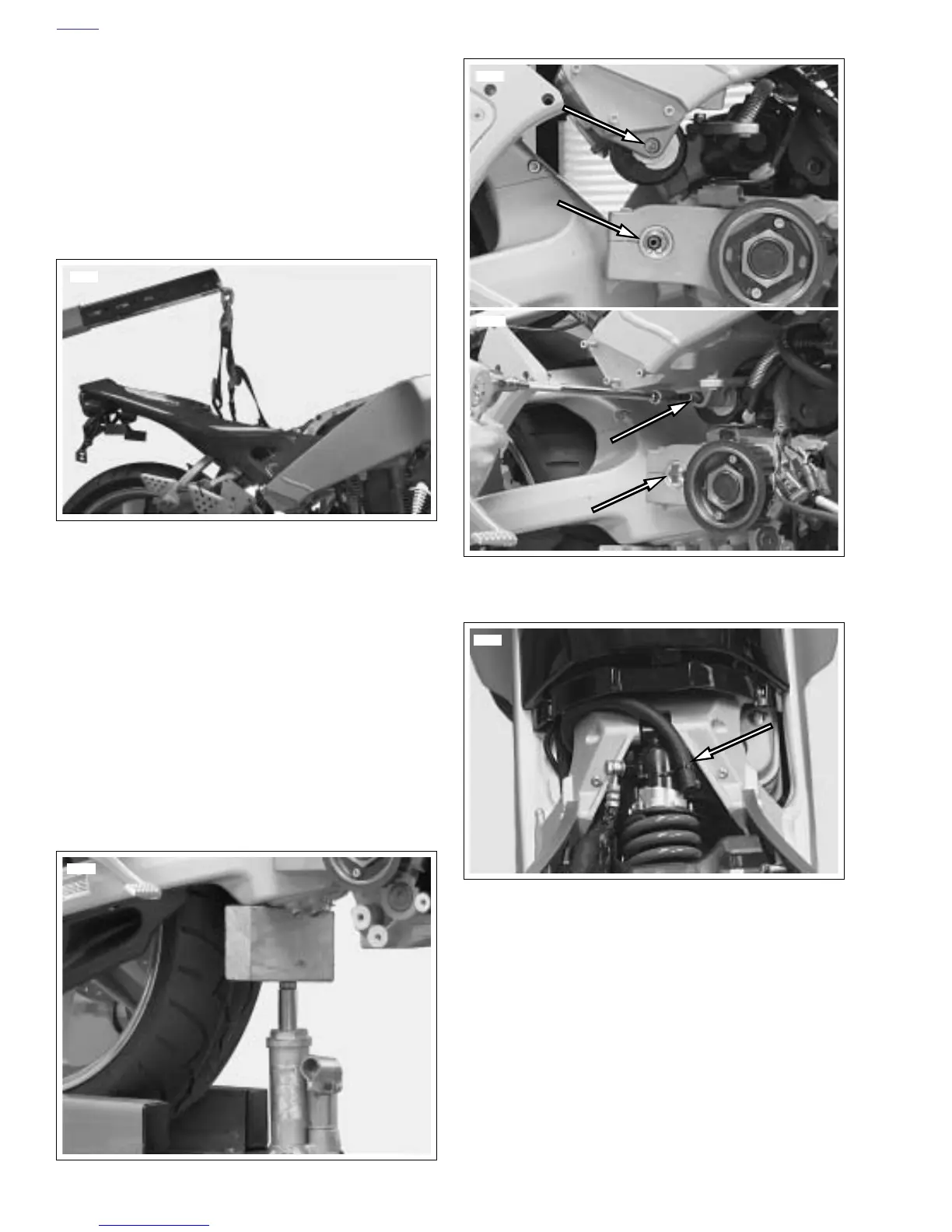
● See Figure 3-22. At this point it is necessary to support
main frame with overhead hoist in order to remove rear
isolator bolt. Failure to do this will result in main frame
dropping slightly.
32. See Figure 3-17. Remove front isolator bolt (6). Remove
front isolator assembly fasteners (5).
33. See Figure 3-23. Remove:
a. Rear isolator bolt.
b. Swingarm pivot shaft.
34. See Figure 3-51. Cut the cable strap holding transmis-
sion vent line and pull vent line out of frame leaving it
attached to engine.
NOTE
The transmission vent line runs up the left side of the frame
and exits underneath the left rear side of the intake cover
assembly
35. See Figure 3-23. Support swingarm/oil tank with wooden
blocks, jack, etc.
36. Lower engine with scissors lift all the way down.
37. Move the engine assembly from under the main frame to
the right side of the lift.
38. Remove engine.
Figure 3-22. Supporting Vehicle for Disassembly (Typical)
Figure 3-23. Supporting the Swingarm (Typical)
8716
8719
Figure 3-24. Rear Isolator Bolt and Swingarm Pivot Shaft
(Typical)
Figure 3-25. Transmission Vent Line
8721
8722
8918