2007 Buell Lightning: Starter 5-15
HOME
DISASSEMBLY, INSPECTION AND
REPAIR
1. See Figure 5-14. Lift rubber boot (1). Remove field wire
nut with washer (2) (metric) to detach field wire (3).
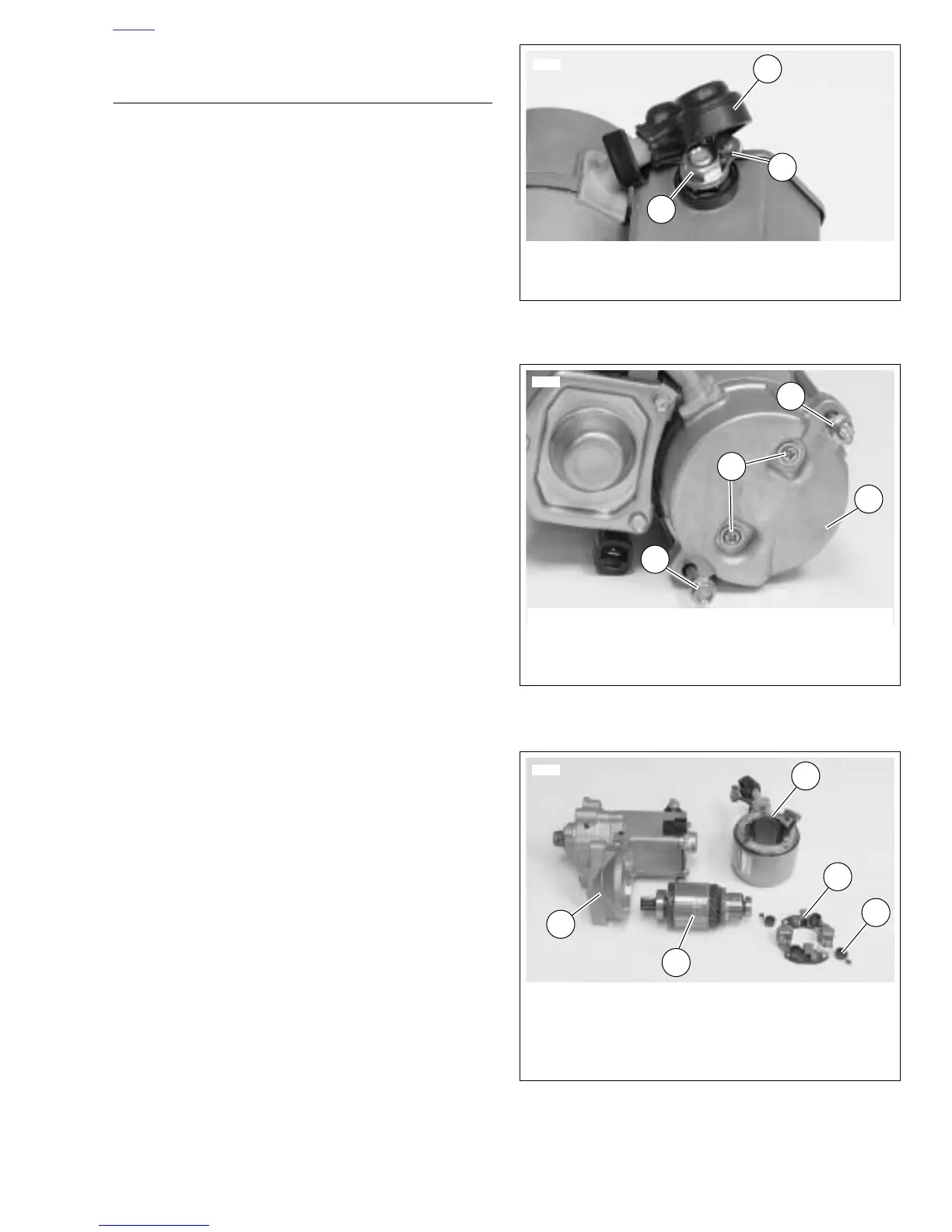
2. See Figure 5-15. Remove both thru-bolts (1, 3).
3. Remove both end cover screws with o-rings (2) and end
cover (4).
4. See Figure 5-16. Use a wire hook to pull upward on
brush springs (3), and lift brushes out of holder (2).
Remove brush holder.
5. Check brush length. Replace all four brushes if length of
any one brush is less than 0.433 in. (11.0 mm).
NOTE
Brushes not available separately. Purchase a
new
field frame
(1) and brush holder (2) to replace brushes.
6. Remove armature (4) and field frame (1).
7. Place armature in lathe or truing stand and check com-
mutator runout and diameter.
a. Commutators with more than 0.016 in. (0.406 mm)
of runout should be replaced or machined on a
lathe.
b. Replace commutators when diameter is less than
1.141 in. (28.981 mm).
c. Check armature bearings. Replace if necessary.
NOTES
●
Do not use sandpaper or emery cloth to remove burrs on
commutator. Otherwise, abrasive grit may remain on
commutator segments; this could lead to excessive
brush wear. Use only the recommended crocus cloth.
●
See Figure 5-17. If an undercutting machine is not avail-
able, undercutting can be done satisfactorily using a thin
hacksaw blade. After undercutting, lightly sand the com-
mutator with crocus cloth to remove any burrs.
8. Check depth of mica on commutator. If undercut is less
than 0.008 in. (0.203 mm), use an undercutting machine
to undercut the mica to 1/32 in. (0.794 mm) deep. The
slots should then be cleaned to remove any dirt or cop-
per dust.
Figure 5-14. Field Wire
Figure 5-15. Removing the Thru-Bolts
Figure 5-16. Starter Components
6007
1
1. Rubber boot
2. Field wire nut with washer (metric)
3. Field wire
3
2
6009
1
3
2
4
1. Lower thru-bolt
2. Screw with O-ring (2)
3. Upper thru-bolt
4. End cover
6010
1
1. Field frame
2. Brush holder
3. Brush spring (4)
4. Armature
5. Solenoid housing
2
3
4
5