2007 Buell Lightning: Drive/Transmission 6-11
HOME
REMOVAL
11WARNING1WARNING
To prevent accidental vehicle start-up, which could
cause death or serious injury, disconnect negative (-)
battery cable before proceeding. (00048a)
1. Remove negative battery cable from battery.
2. Drain the transmission fluid. See 1.8 CLUTCH under 1.8
CLUTCH.
3. Remove primary cover. See 6.2 PRIMARY COVER.
11WARNING1WARNING
Do not attempt to disassemble the clutch without
SPRING COMPRESSING TOOL (Part No. HD-38515-A),
CLUTCH SPRING FORCING SCREW (Part No. HD-38515-
91) and proper eye protection. Otherwise, the highly
compressed diaphragm spring could fly out with great
force which could result in death or serious injury.
4. See Figure 6-13. Attach tools to compress clutch dia-
phragm spring.
a. Thread the CLUTCH SPRING FORCING SCREW
(Part No. HD-38515-91) onto the clutch adjusting
screw.
b. Place the bridge of SPRING COMPRESSING TOOL
(Part No. HD-38515-A) against diaphragm spring.
c. Install bearing and washer.
d. Thread the tool handle onto end of forcing screw.
NOTE
See Figure 6-14. Turn compressing tool handle only the
amount required to release spring seat and remove snap
ring. Excessive compression of diaphragm spring could dam-
age clutch pressure plate.
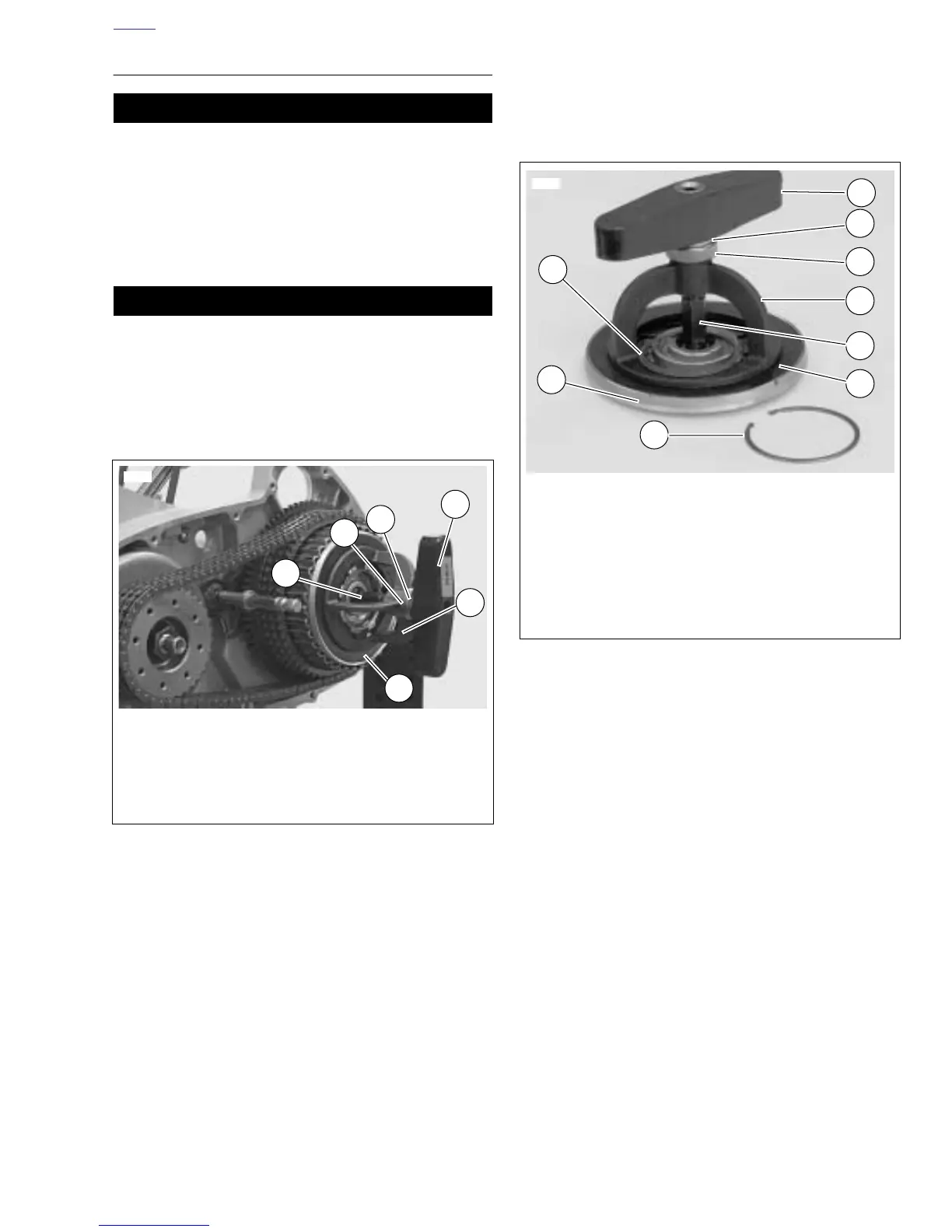
5. See Figure 6-14. Remove pressure plate assembly.
a. Place a wrench on the clutch spring forcing screw
flats to prevent the forcing screw from turning.
b. Turn compressing tool handle clockwise until tool
relieves pressure on retaining ring and spring seat.
Remove and discard retaining ring.
c. Unseat spring seat from the groove in clutch hub
prongs.
d. Remove pressure plate assembly.
6. Remove the clutch pack from the shell/hub assembly.
Figure 6-13. Compressing Clutch Diagram Spring
8807
1. Tool handle
2. Bridge
3. Diaphragm spring
4. Clutch spring forcing screw
5. Bearing
6. Washer
1
6
5
2
4
3
Figure 6-14. Pressure Plate Assembly
6250
1. Tool handle
2. Washer
3. Bearing
4. Bridge
5. Forcing screw
6. Diaphragm spring
7. Snap ring
8. Pressure plate
9. Spring seat
1
3
2
9
8
7
4
6
5