Power cables
5-2 Chapter 5: Power and startup 99-145912-A
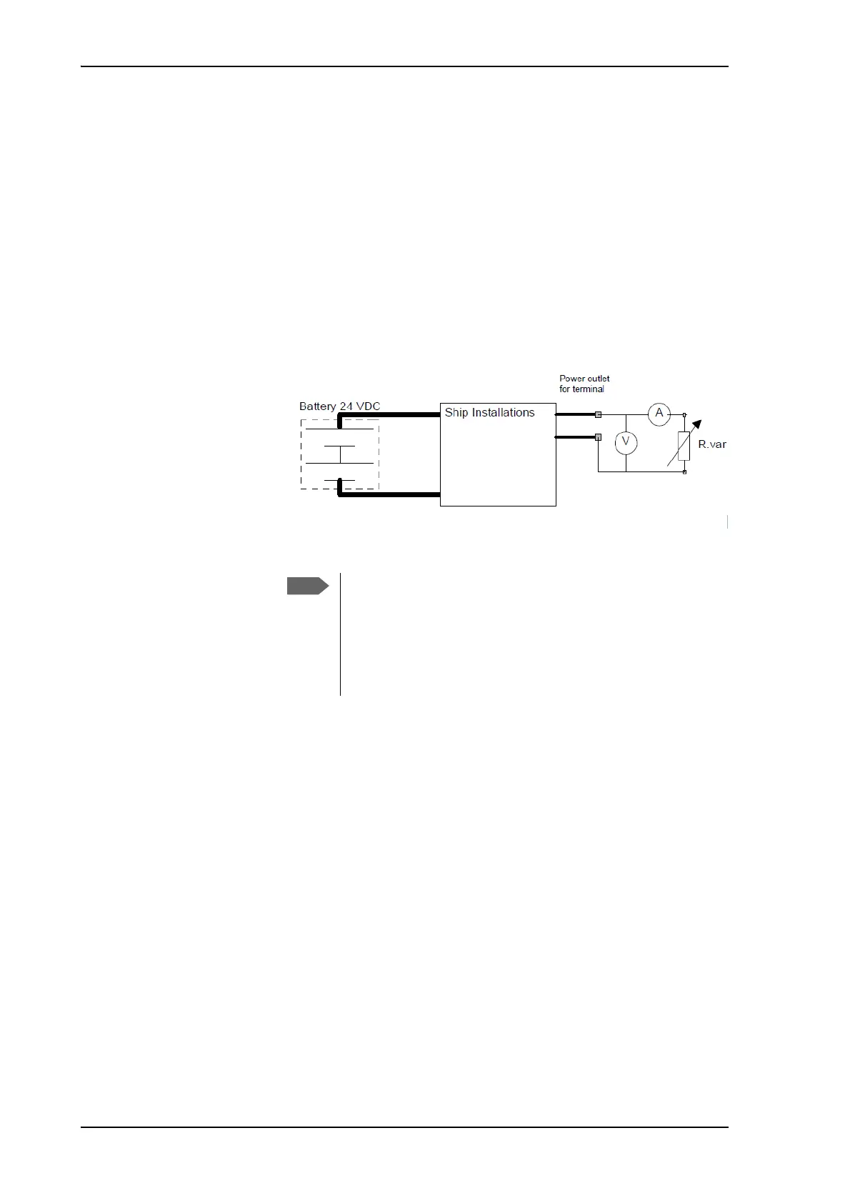
To measure the ship’s source impedance
To measure the ship’s source impedance do as follows:
1. Select a power outlet from the ship’s 24 VDC system.
2. Measure the voltage without load (R.var disconnected).
3. Set the current to e.g. 1 A by adjusting R.var.
4. Measure the corresponding voltage change.
Example: 1 A and 50 mV. Source impedance: 50 mV/1 Amp = 50
mOhm.
Power cable recommendations
The ACU is delivered with a power connector (PCB plug-in connector,
female plug, Weidmuller, Part number 1930050000), which accepts
wires up to AWG10/6 mm
2
.
• When installing the power cable, install positive and negative supply
wires closely together side by side to keep cable inductance low.
• Ensure that cable inductance for the selected cable at the desired
length is less than 50 uH. Approximately 50 m maximum length.
Calculating the maximum power cable length
For 24 VDC operation, the total impedance must be max. 60 mOhm
(R
max
), including the source impedance in the ship installation (R
source
).
The total impedance is the sum of the following:
• Source impedance in the ship installation
• Impedance of the selected power cable
Figure 5-1: Measuring the ship source impedance
If the total impedance is higher than the limits stated in
section , the terminal may become unstable and start to on/off
oscillate.
The total impedance is the sum of the source impedance of
the ship power supply plus the impedance of connected cables
including connectors and joints where cables are extended.

 Loading...


