Installation
2-6 HF SSB transceiver reference manual
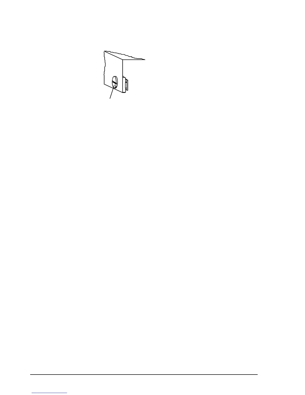
2. Align both cam catch slots with the T-section slides.
Cam catch
(Slot in line
with T slide)
Front section
3. Insert the transceiver side rails into the T-section slides
and push the transceiver fully into the cradle.
4. Apply gentle pressure to the front of the transceiver and
lock it into the cradle by using a flat blade screwdriver to
turn the cam catches one quarter of a turn in either
direction.
Code 118 mounting cradle—top/bottom entry
To mount the cradle:
1. Secure the mounting cradle into position with its spring
clips nearest the front. Ensure there is sufficient space at
the rear of the cradle to take the transceiver heat sink
and connectors.
2. Remove the front and rear fixing screws of the
transceiver side rails (the centre screw to be left
untouched).
Note that adaptor plates have to be fitted to the
transceiver side rails to secure the transceiver to the
cradle.
3. Secure the adaptor plates flush to the transceiver side
rails with the new screws provided, and fit one ‘O’ ring
over each projecting stud. The projecting studs on the
adaptor plates fit into the slides in the cradle.
Installation
2-6 HF SSB transceiver reference manual
2. Align both cam catch slots with the T-section slides.
Cam catch
(Slot in line
with T slide)
Front section
3. Insert the transceiver side rails into the T-section slides
and push the transceiver fully into the cradle.
4. Apply gentle pressure to the front of the transceiver and
lock it into the cradle by using a flat blade screwdriver to
turn the cam catches one quarter of a turn in either
direction.
Code 118 mounting cradle—top/bottom entry
To mount the cradle:
1. Secure the mounting cradle into position with its spring
clips nearest the front. Ensure there is sufficient space at
the rear of the cradle to take the transceiver heat sink
and connectors.
2. Remove the front and rear fixing screws of the
transceiver side rails (the centre screw to be left
untouched).
Note that adaptor plates have to be fitted to the
transceiver side rails to secure the transceiver to the
cradle.
3. Secure the adaptor plates flush to the transceiver side
rails with the new screws provided, and fit one ‘O’ ring
over each projecting stud. The projecting studs on the
adaptor plates fit into the slides in the cradle.