InteliLite
NT
AMF26-P, SW version 2.4, ©ComAp – January 2016 104
AMF26-P-2.4 Reference Guide.pdf
Connection description
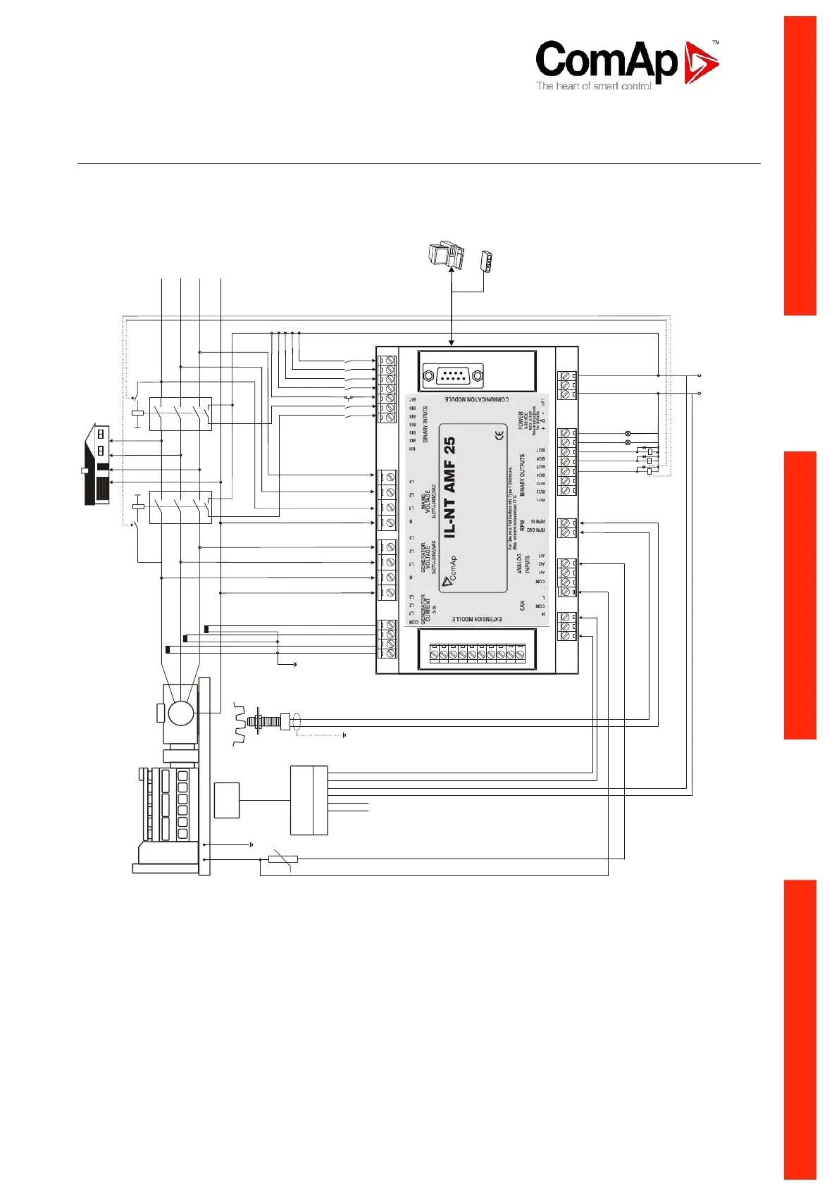
The following diagrams show how to connect the engine control unit to the IL-NT controller:
Engines with J1939 support started via CAN bus
VOLVO PENTA engines (EMS II, EDC III units)
LOAD
ACCES S L OCK
EMERGENCY STO
P
CONTROL
SIGNALS
GEN C.B. FEED-BACK
MAINS C.B. FEED
-BA
CK
DIESEL/GAS ENGINE
RPM
GENERATOR
G
+24 V
L1
L2
L3
N
Generator C.B.
Mains C.B.
SPRINKL ER
REMOTE TEST
RS-232C
Interface
Modem or PC
REMOTE OFF
ALARM
BINARY OUTPUTS
MAINS C.B
.
GEN
C
.B
.
PRESTART
READY TO LOA D
FUEL LEVEL
ECU
8-pole Deutsch
connector
8 7 6 5 4
3
2 1
BO ECU PwrRelay
BO ECU CommOK (EDCIII) / ECU CommError (EMSII)