InteliLite
NT
AMF26-P, SW version 2.4, ©ComAp – January 2016 126
AMF26-P-2.4 Reference Guide.pdf
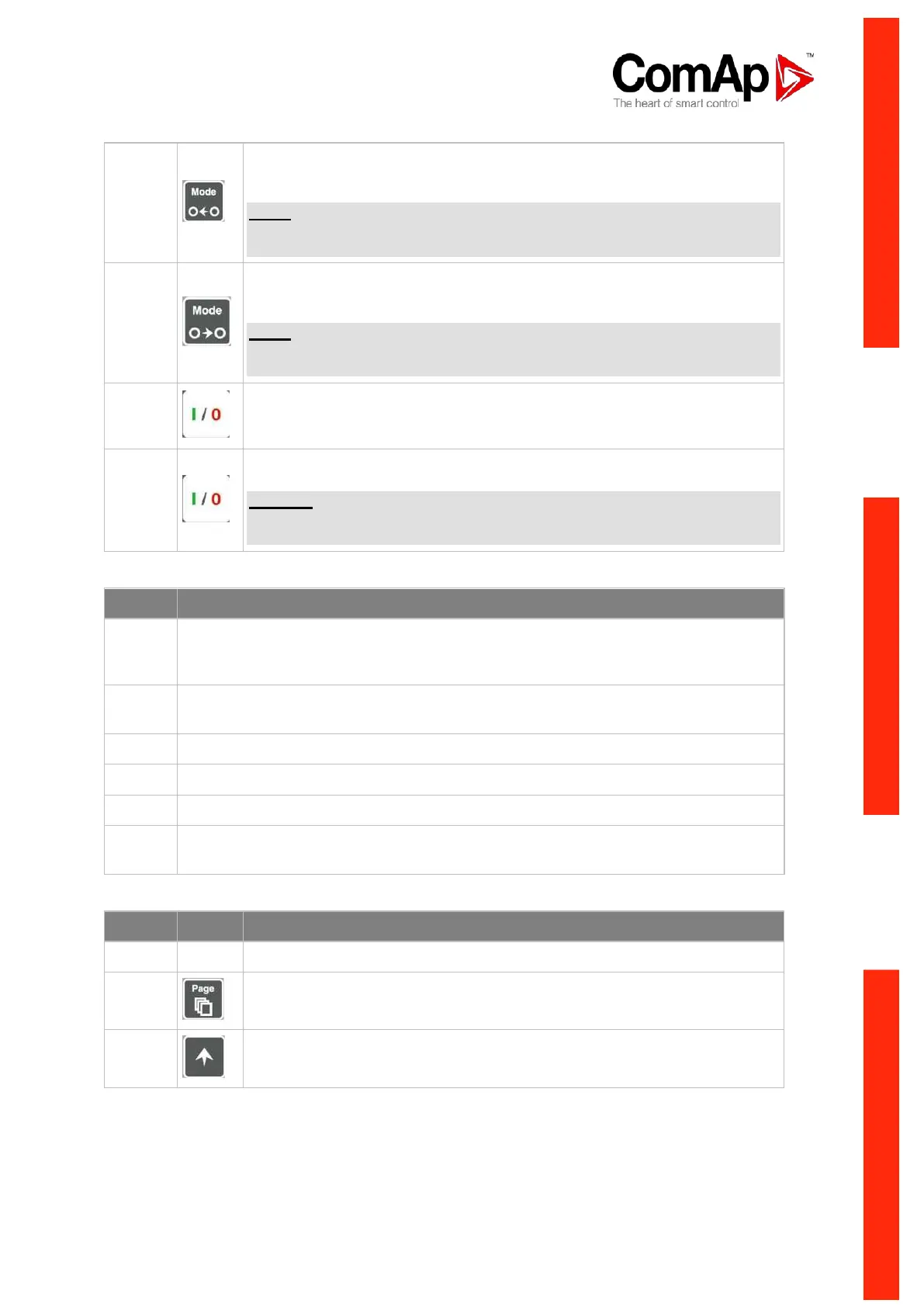
MODE LEFT button. Use this button to change the mode. The button works
only if the main screen with the indicator of currently selected mode is
displayed.
NOTE:
This button will not work if the controller mode is forced by one of binary
inputs Remote OFF, Remote MAN, Remote AUT, Remote TEST.
MODE RIGHT button. Use this button to change the mode. The button works
only if the main screen with the indicator of currently selected mode is
displayed.
NOTE:
This button will not work if the controller mode is forced by one of binary
inputs Remote OFF, Remote MAN, Remote AUT, Remote TEST.
GCB button. Works in MAN and TEST modes only. Press this button to open
or close the GCB manually. Note that certain conditions must be valid
otherwise GCB closing is blocked.
MCB button. Works in MAN and TEST modes only. Press this button to open
or close the MCB manually.
CAUTION!
You can disconnect the load from the mains supply with this button! Be sure
you know well what you are about to do!
GEN-SET OPERATION INDICATORS
Gen-set failure. Red LED starts flashing when gen-set failure occurs. After FAULT
RESET button is pressed, goes to steady light (if an alarm is still active) or is off (if no
alarm is active).
Gen-set voltage OK. Green LED is on if the generator voltage is present and within
limits.
GCB ON. Green LED is on, if GCB is closed. It is driven by GCB feedback signal.
MCB ON. Green LED is on, if MCB is closed. It is driven by MCB feedback signal.
Mains voltage OK. Green LED is on, if mains is present and within limits.
Mains failure. Red LED starts blinking when the mains failure is detected and after
the gen-set has started it lights permanently until the mains failure disappears.
DISPLAY AND CONTROL BUTTONS
Graphic B/W display, 128x64 pixels
PAGE button. Use this button to switch over display pages. See Display
Screens and Pages Structure chapter below this table for more details.
UP button. Use this button to move up or increase a value.