6.5 INHIBIT CONNECTIONS
As with standard PMs, the EL PM90 contains the Inhibit 2 and 3 connections. However, if the EL PM90 is used in conjunction
with a Seating Module, then Inhibit 2 can be routed through to that module via the Seating Module Cable.
The Inhibit connections can be used to limit speed, inhibit drive and /or inhibit actuator channels. Refer to Chapter 3 –
Programming for full details.
6.6 ACTUATOR CONNECTIONS
The EL PM90 has one actuator channel, which can be used in single actuator applications. However, the connection of a Seating
Module consumes this channel, but effectively splits it into a maximum of 5. All actuator channels have a maximum rating of
12A.
NOTE:
The Seating Module does not support automatic end-stop detection. It is therefore recommended that actuators with series
end-stop switches are used.
7 PROGRAMMING
This section describes the programming functions that are associated with the Seating Module.
NOTE:
For any of the following programming to be effective, the parameter Seating Module Enabled must be set to Yes.
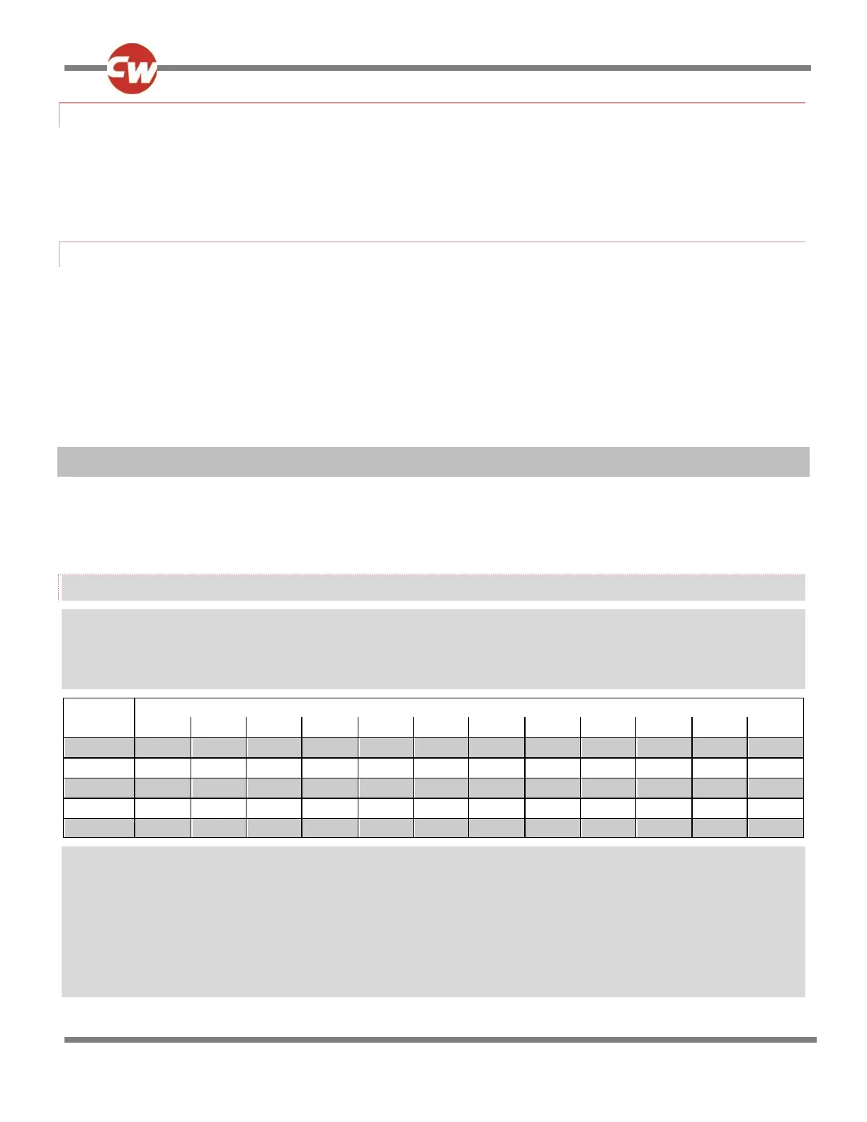
ACTUATOR AXES EXPLAINED
An actuator axis means a particular function of seat control. An axis may involve just one actuator motor, for example, a simple
seat lift; or an axis may involve multiple motors, for example, adjustment of both footrests simultaneously or an anti -shear
recline system. There are 5 actuator motor channels on the SM and a maximum of 12 axes are available. Unlike the ISM, the
SM’s 12 axes are pre-defined in terms of which channels are driven. This is shown in the table below.
For example: when Axis 1 is selected, then Channel 1 will be driven; and when Axis 6 is selected, then both Channels 4 and 5 will
be driven.
For an axis to be available to the user, it must be enabled. The relevant programmable parameter is Axis Enabled.
The R-net SM can support up to 12 actuator axes with a maximum current of 12A across any combination of actuator channels.
The user display for a particular axis is programmable. The relevant parameter is Axis Display.