Programming would be as follows:
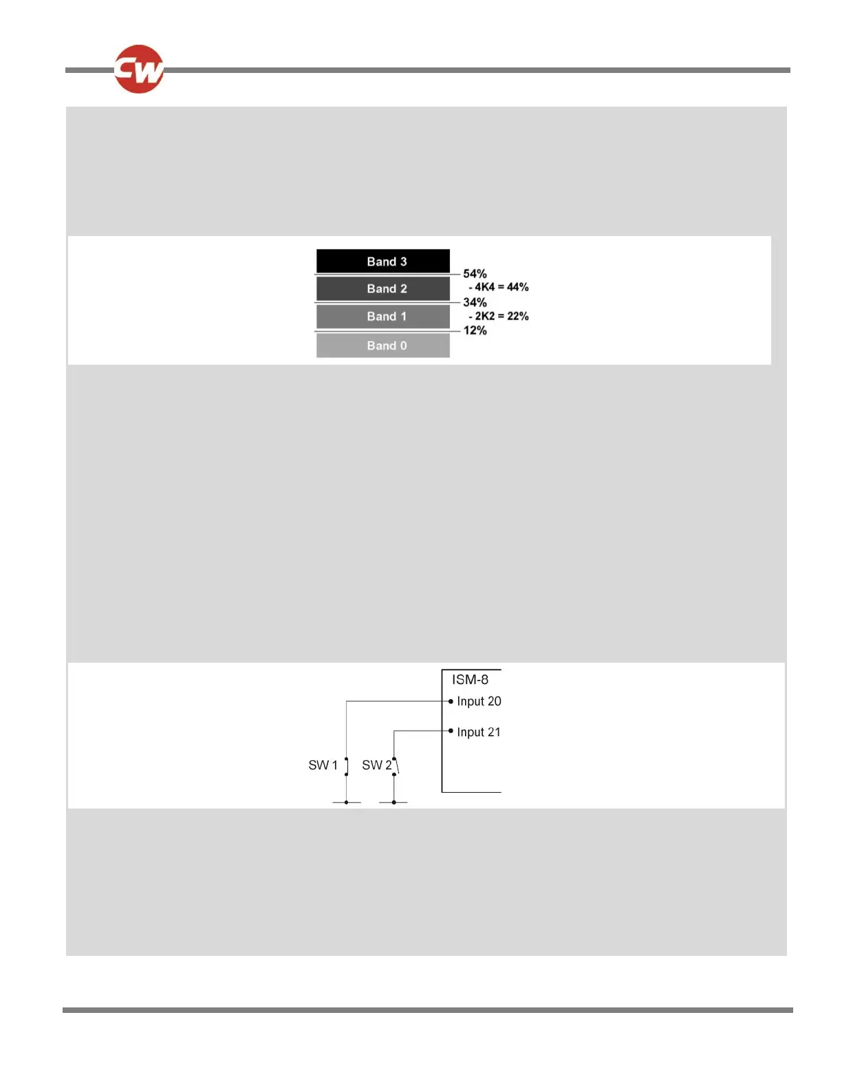
Inputs ISM-8 - Threshold Levels:
Upper Level Threshold 54%
Middle Level Threshold 34%
Lower Level Threshold 12%
This gives a band arrangement as follows.
As good practice, the threshold limits have been chosen so the actual resistance values that trigger a change are in the
approximate center of the bands, thereby eliminating the risk of a system erroneously switchi ng between bands.
The 4 Speed Limits for Drive Inhibit A would need to be set as below:
Inhibit A:
Speed Limit in Band 0 100% Speed Limit in Band 1 50%
Speed Limit in Band 2 25% Speed Limit in Band 3 0%
Actuator Inhibit Examples
Application 1: A wheelchair is fitted with a reclining backrest that has endstop switches connected to the R-net’s Inhibit inputs
20 and 21 on the ISM-8. In this example the switches are installed to be normally closed and the Backrest has been
programmed to use Actuator Channel 2.
A circuit such as follows is used.
The Inhibit input must be assigned to a specific software Inhibit. As this is an Actuator Inhibit, the parameters Actuator In hibits
Channel X - Up: Assign & Down: Assign should be used.
The inputs are therefore assigned to Actuator Inhibits Channel 2 as follows:
Up: Assign - Input 20
Down: Assign - Input 21
As these inputs are connected to the ISM-8 the Threshold levels must be set in the parameter Inputs - ISM-8.